ATEN CS1708i User Manual
Kvm on the net
Hide thumbs
Also See for CS1708i:
- User manual (216 pages) ,
- Specifications (5 pages) ,
- Quick start manual (2 pages)
Table of Contents
Advertisement
Quick Links
Download this manual
See also:
User Manual
Advertisement
Table of Contents

Related Manuals for ATEN CS1708i


Summary of Contents for ATEN CS1708i
- Page 1 KVM On the NET CS1708i / CS1716i User Manual www.aten.com...
-
Page 2: Rohs
CS1708i / CS1716i User Manual FCC Information This is an FCC Class A product. In a domestic environment this product may cause radio interference in which case the user may be required to take adequate measures. This equipment has been tested and found to comply with the limits for a Class A digital device, pursuant to Part 15 of the FCC Rules. -
Page 3: User Information
CS1708i / CS1716i User Manual User Information Online Registration Be sure to register your product at our online support center: International http://support.aten.com North America http://www.aten-usa.com/product_registration Telephone Support For telephone support, call this number: International 886-2-8692-6959 China 86-10-5255-0110 Japan 81-3-5615-5811 Korea... -
Page 4: Package Contents
Please visit our website to download the most up-to-date version of the manual. © Copyright 2009–2013 ATEN® International Co., Ltd. Manual Part No. PAPE-0317-AT5G F/W Version: 1.3.127 Manual Date: 2013-05-22 ATEN and the ATEN logo are registered trademarks of ATEN International Co., Ltd. All rights reserved. -
Page 5: Table Of Contents
CS1708i ........ - Page 6 CS1708i / CS1716i User Manual 3. Basic Operation Port Selection ..........23 Manual .
- Page 7 CS1708i / CS1716i User Manual 6. Administration Introduction ..........53 General Information .
- Page 8 CS1708i / CS1716i User Manual The Main Page ..........85 The List Function.
- Page 9 CS1708i.........
- Page 10 CS1708i / CS1716i User Manual CS1716i ..........155 Supported KVM Switches .
-
Page 11: About This Manual
CS1708i / CS1716i User Manual About this Manual This user manual is provided to help you get the most from your CS1708i / CS1716i system. It covers all aspects of installation, configuration and operation. An overview of the information found in the manual is provided below. -
Page 12: Terminology
CS1708i / CS1716i User Manual Chapter 12, The Firmware Upgrade Utility, explains how to use this utility to upgrade the CS1708i / CS1716i's firmware with the latest available versions. An Appendix, provides specifications and other technical information regarding the CS1708i / CS1716i. -
Page 13: Conventions
For information about all ATEN products and how they can help you connect without limits, visit ATEN on the Web or contact an ATEN Authorized Reseller. Visit ATEN on the Web for a list of locations and telephone numbers: International http://www.aten.com... - Page 14 CS1708i / CS1716i User Manual This Page Intentionally Left Blank...
-
Page 15: Introduction
Java 2 enabled operating systems. The client software allows operators to exchange keyboard, video and mouse signals with the computers attached to the CS1708i / CS1716i just as if they were present locally and working on the equipment directly. With the Panel Array feature, the video output of up to 8 or 16 computers can be displayed at the same time. - Page 16 For local access, the CS1708i / CS1716i supports resolutions of up to 2048 x 1536. For remote access, the switches support up to 1600 x 1200 @ 60Hz / 24 bit color depth.
-
Page 17: Features
Features A single console controls up to 8 (CS1708i) or 16 (CS1716i) computers Daisy chain up to 15 additional units – control up to 128 (CS1708i) or 256 (CS1716i) computers from a single console Auto-sensing of station's position on daisy chained installations; no need for manual dip switch setting;... - Page 18 CS1708i / CS1716i User Manual Superior video quality – up to 2048 x 1536; DDC2B for the local console; up to 1600 x 1200 @ 60Hz / 24 bit color depth for remote sessions Video DynaSync– stores the console monitor's EDID (Extended Display...
-
Page 19: Requirements
General For best results, we recommend that the computers used to access the CS1708i / CS1716i have at least a P III 1 GHz processor, and that their screen resolution is set to 1024 x 768 For best results, we recommend an Internet connection speed of at least... -
Page 20: Cables
CS1708i / CS1716i User Manual Cables Substandard cables might damage the connected devices or degrade overall performance. For optimum signal integrity and to simplify the layout use the high quality custom cable sets described below. Function Length Part Number KVM switch to KVM switch 0.6 m... -
Page 21: Browsers
1. Introduction Browsers Supported browsers for users that log into the KVM On the NET switch include the following: Browser Version 6 and higher Firefox 1.5 and higher Mozilla 1.7 and higher Safari 4.0 and higher Opera 9.0 and higher Netscape 8.1 and higher... -
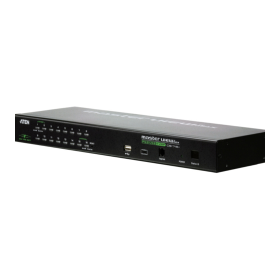
Page 22: Components
CS1708i / CS1716i User Manual Components Front Panel CS1708i 1&2 CS1716i 1&2... - Page 23 Lights to indicate that the switch is powered up and ready to operate. Station ID The CS1708i / CS1716i station ID is displayed here. If this is a single station installation (see page 19), or the first station of a daisy chained installation (see page 21), the switch has a station ID of 01.
-
Page 24: Rear Panel
CS1708i / CS1716i User Manual Rear Panel CS1708i 4 5 6 CS1716i... - Page 25 Power Jack The power adapter cable plugs in here. LAN Port The cable that connects the CS1708i / CS1716i to the Internet, LAN, or WAN plugs in here. The LED on the left side of the port indicates data transmission speed: Orange for 10 Mbps;...
- Page 26 CS1708i / CS1716i User Manual This Page Intentionally Left Blank...
-
Page 27: Hardware Setup
Overview For convenience and flexibility that allows mixing PS/2 and USB interfaces, as well as multiple platforms, the CS1708i / CS1716i design utilizes custom KVM cables that serve as intermediaries between the switch and the connected computers (refer to the Cable Connection Diagrams, on page 20). -
Page 28: Stacking And Rack Mounting
CS1708i / CS1716i User Manual Stacking and Rack Mounting The CS1708i / CS1716i can be stacked on the desktop or rack mounted at the front or rear of the rack. The following sections take you through the procedures for each method. -
Page 29: Rack Mounting - Front
2. Hardware Setup Rack Mounting – Front 1. Remove the screws from the left and right sides of the switch (2 screws total) near the front of the switch. 2. Use the M3 x 8 Phillips hex head screws supplied with the rack mounting kit to screw the rack mounting brackets into the sides near the front of the unit. - Page 30 CS1708i / CS1716i User Manual (Continued from previous page.) 3. Place the KVM switch in the rack. Position it so that the holes in the mounting brackets line up with the holes in the rack. Secure the mounting brackets to the front of the rack.
-
Page 31: Rack Mounting - Rear
2. Hardware Setup Rack Mounting – Rear 1. Remove 1 screw each from the left and right sides of the switch (2 screws total) near the rear of the unit. 2. Use the M3 x 8 Phillips hex head screws supplied with the rack mounting kit to screw the rack mounting brackets into the sides near the rear of the unit. - Page 32 CS1708i / CS1716i User Manual (Continued from previous page.) 3. Place the KVM switch in the rack. Position it so that the holes in the mounting brackets line up with the holes in the rack. Secure the mounting brackets to the rear of the rack.
-
Page 33: Single Station Installation
(See KVM Cable Installation Diagrams on the following page.) 4. Plug the power adapter cable into the CS1708i / CS1716i power jack, then plug the power adapter into an AC power source. After all the equipment has been connected up, power on the computers. -
Page 34: Cable Connection Diagrams
CS1708i / CS1716i User Manual Cable Connection Diagrams Console Cable Installation Diagram PS/2 KVM Cable Installation Diagrams USB KVM Cable Connection PS/2 KVM Cable Connection... -
Page 35: Daisy Chaining
2. Use a daisy chain cable set (described in the Cables section, page 6), to connect the Chain Out port of the CS1708i / CS1716i to the Chain In port of the first chained unit. 3. To add additional switches to the chain, use daisy chain cable sets to connect the Chain Out port of the parent switch to the Chain In port of the child switch. - Page 36 CS1708i / CS1716i User Manual Daisy Chain Installation Diagram...
-
Page 37: Basic Operation
OSD/GUI The CS1708i / CS1716i provides two menu driven interfaces to the port selection procedure: A text-based OSD (On Screen Display), when you log in from a local console; and a GUI (Graphical User Interface) when you log in remotely over the internet. -
Page 38: Hot Plugging
CS1708i / CS1716i User Manual Hot Plugging The CS1708i / CS1716i supports hot plugging – components can be removed and added back into the installation by unplugging and replugging their cables from the switch’s ports without the need to shut the unit down. In order for hot... -
Page 39: Port Id Numbering
06. It’s Port ID would be: 12-06. Powering Off and Restarting If it becomes necessary to power off a CS1708i / CS1716i, do the following before restarting it: 1. Shut down all the computers that are attached to the CS1708i / CS1716i. -
Page 40: Usb Peripheral Devices
The front panel USB port is available to connect a USB peripheral device (flash drive, CD-ROM drive, printer, etc.) to the CS1708i / CS1716i. Any computer connected to the CS1708i / CS1716i can access the USB peripheral on a one- at-a-time basis. -
Page 41: Local Console Operation
Local Console Operation Overview When setting up your CS1708i / CS1716i installation for the first time, we recommend doing it from the local console. Local console operation offers a menu driven On Screen Display (OSD) to handle computer control and switching operations. -
Page 42: Osd Main Screen
CS1708i / CS1716i User Manual OSD Main Screen When you invoke the OSD, a screen similar to the one below appears: The diagram depicts the administrator's main screen. The user main screen does not show the F4 and F6 functions, since these are reserved for the administrator and can't be accessed by users. -
Page 43: Osd Navigation
4. Local Console Operation OSD Navigation To dismiss the menu, and deactivate OSD, click the X at the upper right corner of the OSD window; or press [Esc]. To log out, click F8 at the top of the main screen, or press [F8]. To move up or down through the list one line at a time, Click the Up and Down Triangle symbols ( ) or use the Up and Down Arrow Keys. -
Page 44: Osd Functions
CS1708i / CS1716i User Manual OSD Functions OSD functions are used to configure and control the OSD. For example, you can rapidly switch to any port, scan selected ports, limit the list you wish to view, designate a port as a quick view port, create or edit a port name, or make OSD setting adjustments. -
Page 45: F2: List
4. Local Console Operation F2: LIST This function lets you broaden or narrow the scope of which ports the OSD displays (lists) on the Main OSD Screen. Many of the OSD functions only operate on the computers that are listed on the Main OSD Screen. The submenu choices and their meanings are given in the table below. -
Page 46: F3: Set
CS1708i / CS1716i User Manual F3: SET This function allows the administrator and each user to set up his own working environment. A separate profile for each is stored by the OSD and is activated according to the username that was provided during login. - Page 47 4. Local Console Operation Setting Function SCAN–SKIP Selects which computers will be accessed under Skip Mode (see MODE F5: SKP, page 36), and Auto Scan Mode (see F7: SCAN, page 38). Choices are: see Port ALL - All the Ports which have been set Accessible ( Access , page 99), POWERED ON - Only those Ports which have been set Accessible...
-
Page 48: F4: Adm
Setting Function SET IP This entry allows you to select whether to assign the CS1708i / ADDRESS CS1716i’s IP address dynamically (DHCP), or to give it a fixed IP address. Press [Space] to toggle between the choices. - Page 49 4. Local Console Operation Setting Function RESTORE This function is used to undo all changes and return the setup to DEFAULT the original factory default settings (see Restoring Factory Default VALUES Settings, page 157). CLEAR THE This function is similar to Restore Default Values. The difference is NAME LIST that it also clears the Names settings along with undoing all changes and returning the setup to the original factory default...
-
Page 50: F5: Skp
CS1708i / CS1716i User Manual Setting Function FIRMWARE In order to upgrade the CS1708i / CS1716i firmware (see UPGRADE page 129), you must first enable Firmware Upgrade mode with this setting. When you bring up this menu, the current firmware version levels are displayed. -
Page 51: F6: Brc
4. Local Console Operation F6: BRC F6 is an administrator only function. When Broadcast (BRC) mode is in effect, commands sent from the console are broadcast to all available computers on the installation. This function is particularly useful for operations that need to be performed on multiple computers, such as performing a system wide shutdown, installing or upgrading software, etc. -
Page 52: F7: Scan
CS1708i / CS1716i User Manual F7: SCAN This function (also referred to as Auto Scan Mode) allows you to automatically switch the KVM focus among the available computers at regular intervals so that you can monitor their activity without having to take the trouble of switching manually. -
Page 53: F8: Lout
4. Local Console Operation F8: LOUT Clicking the F8 field, or pressing [F8] logs you out of OSD control of the computers, and blanks the console screen. This is different from simply pressing [Esc] when you are at the main screen to deactivate the OSD. With this function you must log in all over again to regain access to the OSD, whereas with [Esc], all you have to do to reenter the OSD is tap the OSD hotkey. -
Page 54: Hotkey Operation
CS1708i / CS1716i User Manual Hotkey Operation Overview In addition to the OSD, the CS1708i / CS1716i also supports port control and configuration options directly from the keyboard with the use of hotkey combinations. Note: To use this function Hotkey Command Mode must be enabled. -
Page 55: Invoking Hotkey Mode
4. Local Console Operation Invoking Hotkey Mode All Hotkey operations begin by invoking Hotkey Mode. Invoking Hotkey Mode takes three steps: 1. Hold down the Num Lock key; 2. Press and release the minus key; 3. Release the Num Lock key: [Num Lock] + [-];... -
Page 56: Hotkey Port Control
CS1708i / CS1716i User Manual Hotkey Port Control Selecting the Active Port Each KVM port is assigned a Port ID (see Port ID Numbering, page 25). You can directly access any computer on the installation with a Hotkey combination that specifies the Port ID of the KVM port that the computer is connected to. - Page 57 4. Local Console Operation Auto Scan Mode Auto Scan Mode automatically switches among all the KVM ports that have been set as accessible under Scan–Skip Mode at regular intervals, so that their activity cane be monitored automatically. (See SCAN–SKIP MODE, page 33.) To start Auto Scan Mode, do the following: 1.
-
Page 58: Skip Mode
CS1708i / CS1716i User Manual Skip Mode This feature allows you to switch between computers in order to monitor them manually. You can dwell on a particular port for as long as you like – as opposed to auto scanning, which automatically switches after a fixed interval. -
Page 59: Hotkey Configuration Operations
Hotkey Beeper Control The Beeper (see ACTIVATE BEEPER, page 35) can be hotkey toggled On and Off. When the beeper is set to On, the CS1708i / CS1716i beeps when it switches ports. To toggle the Beeper, do the following: 1. -
Page 60: Setting The Port Operating System
Sets the Port OS to Sun After pressing a function key you automatically exit Hotkey mode. Restore Default Values This administrator only hotkey restores the CS1708i / CS1716i default values (see RESTORE DEFAULT VALUES, page 35). To restore the default values, do the following: 1. -
Page 61: Hotkey Summary Table
4. Local Console Operation Hotkey Summary Table The following table summarizes Hotkey operations on the CS1708i / CS1716i: [Num Lock] + [-] [A] [Enter] Invokes Auto Scan mode. When Auto Scan mode is in effect, [P] or left-click pauses auto-scanning. - Page 62 CS1708i / CS1716i User Manual This Page Intentionally Left Blank...
-
Page 63: Browser Login
Logging In To log in from an Internet browser, do the following: 1. Open your browser and specify the IP address of the CS1708i / CS1716i you want to access in the browser's URL location bar. Note: 1. For security purposes, a login string may have been set by the administrator. - Page 64 (see Trusted Certificates, page 151 for details.) The CS1708i / CS1716i login page appears: 3. Provide a valid Username and Password (set by the CS1708i / CS1716i administrator – see User Management, page 67), then click Login to continue.
- Page 65 5. Browser Login After you have successfully logged in, the CS1708i / CS1716i Main Webpage appears: Note: The makeup of the Main Webpage varies depending on the User type and permissions (see User Management, page 67). Not all of the screen elements appear for all users.
-
Page 66: Main Webpage Elements
CS1716i accessible to all platforms that have the Java Runtime Environment (JRE) installed. Log: All the events that take place on the CS1708i / CS1716i are recorded in a log file. If you have the proper permission (see User Management, page 67), clicking this icon displays the contents of the log file. -
Page 67: Administration
Administration Introduction The administration utilities, represented by the icons located across the top of the web page, are used to configure the CS1708i / CS1716i’s operating environment. This chapter discusses each of them in turn. Note: 1. As you make your configuration changes in each dialog box, click Apply to save them. -
Page 68: General Information
Device Name: To make it easier to manage installations that have more than one CS1708i / CS1716i, each one can be given a name. To assign a name for the CS1708i / CS1716i, key in one of your choosing here (16 characters max.), then click Apply. -
Page 69: Network
6. Administration Network The Network dialog is used to specify the CS1708i / CS1716i's network environment. Access Ports If a firewall is being used, the Administrator can specify the port numbers that the firewall will allow and the firewall accordingly. If a port other than the default is set, users must specify the port number as part of the IP address when they log in. -
Page 70: Ipv4 Configuration
IP address, Subnet Mask, and Default Gateway fields with settings appropriate for your network. Note: If the CS1708i / CS1716i is on a network that uses DHCP to assign network addresses, and you need to ascertain its IP address, see IP Address Determination, page 145, for information. -
Page 71: Ipv6 Configuration
IP address, Prefix Length, and Default Gateway fields with settings appropriate for your network. Note: If the CS1708i / CS1716i is on a network that uses DHCP to assign network addresses, and you need to ascertain its IP address, see IP Address Determination, page 145, for information. -
Page 72: Ip Installer Settings
IP Installer utility. See IP Installer, page 145 for details. Note: 1. If you select View Only, you will be able to see the CS1708i / CS1716i in the IP Installer’s Device List, but you will not be able to change the IP address. -
Page 73: Security
If any User Station Filters have been configured, they appear in the IP Filter and/or MAC Filter list boxes. IP and MAC Filters control access to the CS1708i / CS1716i based on the IP and/or MAC addresses of the computers attempting to connect. A maximum of 100 IP filters and 100 MAC filters are allowed. -
Page 74: Adding Filters
CS1708i / CS1716i User Manual Adding Filters To add an IP filter, do the following: 1. Click Add. A dialog box similar to the one below appears: 2. Specify the filter address in the dialog box (for example, 192.168.0.200), then click OK. -
Page 75: Ip Filter / Mac Filter Conflict
Delete. Login String The Login String lets the Administrator specify a login string that users must include (in addition to the IP address) when they access the CS1708i / CS1716i with a browser. For example: 192.168.0.126/CS1716i Note: 1. There must be a forward slash between the IP address and the string. -
Page 76: Anms
CS1708i / CS1716i User Manual ANMS The Advanced Network Management Settings page allows you to set up login authentication and authorization management from external sources. It is divided into several sections, each of which is described in the sections that... -
Page 77: Radius Settings
2. Fill in the IP addresses and port numbers for the Preferred and Alternate RADIUS servers. 3. In the Timeout field, set the time in seconds that the CS1708i / CS1716i waits for a RADIUS server reply before it times out. -
Page 78: Radius Examples
User can only view station 02 CC Management Settings To allow authorization for the CS1708i / CS1716i through a CC (Control Center) server, check Enable and fill in the CC Server’s IP address and the port that it listens on in the appropriate fields. - Page 79 For LDAP, the default port number is 389; for LDAPS, the default port number is 636. Timeout Set the time in seconds that the CS1708i / CS1716i waits for an LDAP or LDAPS server reply before it times out. LDAP Administrator Consult the LDAP / LDAPS administrator to ascertain the appropriate entry for this field.
-
Page 80: Log Server
CS1708i / CS1716i User Manual Log Server Important transactions that occur on the CS1708i / CS1716i, such as logins and internal status messages, are kept in an automatically generated log file Specify the MAC address of the computer that the Log Server runs on in the MAC address field. -
Page 81: User Management
6. Administration User Management The User Management page is used to create and manage user profiles. Up to 64 user profiles can be established. To add a user profile, fill in the information asked for in the right panel, then click Add. The new user’s name appears in the left panel. To delete a user profile, select it from the names displayed in the left panel, and click Remove. - Page 82 CS1708i / CS1716i via the Java Client software. Configure: Checking Configure gives a user Administrator privileges, and allows the user to set up and modify the CS1708i / CS1716i's operating environment. Log: Checking Log allows a user to view the contents of the log file.
-
Page 83: Customization
If there is no user input for the amount of time specified here, the user is automatically logged out, and must log in again before the CS1708i / CS1716i can be accessed. The default is 0, which means that the Timeout function is disabled. -
Page 84: Working Mode
Parameter Explanation Enable ICMP If ICMP is enabled, the CS1708i / CS1716i can be pinged and an IP address can be assigned with the ARP command. If it is not enabled, the device cannot be pinged, nor can it be assigned an IP address with the ARP command. -
Page 85: Reset
6. Administration Manual If Automatic synching isn’t able to keep the pointers in sync, selecting Manual provides you with a number of methods to bring them back into sync: Perform a video and mouse auto sync by clicking the Video Settings icon on the Control Panel (see page 77). -
Page 86: Maintenance
To upgrade the icard firmware, do the following: 1. Download the new firmware file to your computer. 2. Open your browser; log in to the CS1708i / CS1716i; and click the Maintenance icon. 3. Click Browse (to the right of the Firmware File text input box); navigate to the directory that the new firmware file is in and select the file. -
Page 87: Backup Configuration / User Accounts / Port Names
6. Administration Backup Configuration / User Accounts / Port Names This section of the page gives you the ability to back up the CS1708i / CS1716i’s configuration, user profile information, and port names. To perform a backup, do the following: 1. -
Page 88: Restore Configuration / User Accounts / Port Names
Backed up Configuration information, User Accounts, and Port Names can be restored with this section of the page. Information currently configured on the CS1708i / CS1716i will be replaced with the information that you restore. To restore a previous backup, do the following: 1. -
Page 89: The Windows Client Viewer
Chapter 7 The Windows Client Viewer Starting Up The Windows Client Viewer is only available when you log in using the Microsoft Internet Explorer (IE) browser. After you log in (see Logging In, page 49), click the Open Windows Client icon at the left of the page. (Continues on next page.) - Page 90 A second or two after you click the Open Windows Client link, you connect to the switch: The CS1708i / CS1716i’s GUI comes up with the Main page displayed in the center of the screen and a Control Panel displayed at the lower right. The GUI consists of three pages –...
-
Page 91: The Control Panel
7. The Windows Client Viewer After switching to a port, you can work on the remote system via the screen display on your monitor just as if it were your local system. You can maximize the window, drag the borders to resize the window; or use the scrollbars to move around the screen. - Page 92 CS1708i / CS1716i User Manual Icon Function Click to send a Ctrl+Alt+Del signal to the remote system. Click the keyboard to bring up the on-screen keyboard. Click the arrowhead to bring up the list of available keyboard languages (see The On-Screen Keyboard, page 84).
-
Page 93: Hotkey Setup
7. The Windows Client Viewer Hotkey Setup Various configuration actions related to the keyboard, video, and mouse can be performed via hotkey combinations. The actions performed by the Hotkeys are listed at the left of the panel; the hotkeys that invoke them are shown to the right. -
Page 94: Configuring The Hotkeys
If you substitute the F12 key, for example, you would use [F12 + Tab] and [Ctrl + F12 + Del]. Exit remote location Breaks the connection to the CS1708i / CS1716i and returns you to local operation. Configuring the Hotkeys... -
Page 95: Video Settings
7. The Windows Client Viewer Video Settings The Video Settings dialog box allows you to adjust the placement and picture quality of the remote screen display on your monitor. The meanings of the adjustment options are given in the table below: Option Usage Screen Position... -
Page 96: The Message Board
CS1708i / CS1716i User Manual The Message Board To alleviate the possibility of access conflicts resulting from multiple user logins, the CS1708i / CS1716i provides a message board that allows users to communicate with each other: The Button Bar The buttons on the Button Bar are toggles. Their actions are described in the... -
Page 97: Message Display Panel
7. The Windows Client Viewer Message Display Panel Messages that users post to the board - as well as system messages - display in this panel. If you disable Chat, however, messages that get posted to the board won't appear. Compose Panel Key in the messages that you want to post to the board in this panel. -
Page 98: The On-Screen Keyboard
CS1708i / CS1716i User Manual The On-Screen Keyboard The CS1708i / CS1716i supports an on-screen keyboard, available in multiple languages, with all the standard keys for each supported language. Click this icon to pop up the on-screen keyboard: One of the major advantages of the on-screen keyboard is that if the keyboard languages of the remote and local systems aren’t the same, you don’t have to... -
Page 99: The Main Page
7. The Windows Client Viewer The Main Page This page lists all of the CS1708i / CS1716i's ports and governs port access. Selecting a port and double clicking it switches you to the device on that port. Note: The administrator selects which ports are accessible to each user with the User Management function (see page 98 for details). -
Page 100: The List Function
CS1708i / CS1716i User Manual The List Function The List Function lets you broaden or narrow the scope of which ports the GUI displays (lists) in the Main Screen. To invoke the List Function, click the arrow at the upper right corner of the panel, or press [F3]:... - Page 101 7. The Windows Client Viewer The drop down list on the left offers four fixed choices as shown in the table, below: Choice Meaning Lists all of the ports on the installation. Powered On Lists only the ports that have their attached devices powered on.
-
Page 102: Port Names
CS1708i / CS1716i User Manual Port Names To help remember which computer is attached to a particular port, every port can be given a name. This field allows the Administrator to create, modify, or delete port names. To configure a port name: 1. - Page 103 7. The Windows Client Viewer 3. When you have finished editing the port name, click anywhere outside of the input box to complete the operation.
-
Page 104: Port Operation
User Management function (see page 98 for details). The Port Toolbar The GUI provides a toolbar to help you control the CS1708i / CS1716i from within the captured port. To bring up the toolbar, tap the OSD Hotkey twice (Scroll Lock is the default OSD Hotkey). -
Page 105: Hotkey Summary Table
Click to skip directly to the first accessible port on the entire installation. Click to skip directly to the first accessible port previous to the current one. Click to begin Auto Scan Mode. The CS1708i / CS1716i automatically switches among the ports that were selected for Auto Scanning under the Configuration Scan Select function (see Scan Select, page 96). -
Page 106: Auto Scan Mode
CS1708i / CS1716i User Manual Auto Scan Mode When Auto Scan Mode is invoked, the CS1708i / CS1716i automatically switches among all the ports that are accessible to the currently logged on user at regular intervals, so that the user can monitor their activity automatically. -
Page 107: Panel Array Mode
Clicking on the Port Toolbar's Panel icon invokes Panel Array Mode. Under this mode the screen is divided into a grid of panels: Each panel represents one of the CS1708i / CS1716i's ports. The port’s ID displays in the top center of the panel. - Page 108 CS1708i / CS1716i User Manual The panel array toolbar (shown at the bottom right of the screenshot) provides shortcut navigation and control of the panel array. The meanings of the toolbar icons are explained in the table below: Icon Meaning Move back four panels.
-
Page 109: The Configuration Page
The Configuration Page The GUI’s Configuration page allows users to set up their own, individual, working environments. The CS1708i / CS1716i stores a separate configuration record for each user profile, and sets up the working configuration according to the Username that is used to log in. - Page 110 If there is no Operator input for the amount of time set with this function, the Operator is automatically logged out. A login is necessary before the CS1708i / CS1716i can be accessed again. Enter a value from 0 – 180 minutes. The default is 30 minutes. 0 disables the function.
-
Page 111: The Administration Page
Click in the field to key in the name. MAC Address This item displays the CS1708i / CS1716i’s MAC address. Firmware Ver This item displays the current firmware version number. You can reference it to see if there are newer versions available on the Altusen website. -
Page 112: User Management
CS1708i / CS1716i User Manual User Management The User Management dialogs are used to create and manage user profiles. Up to 64 user profiles can be established. Up to 32 users can log in concurrently. To delete a user profile, select it in the list box, and click Remove. -
Page 113: Port Access
7. The Windows Client Viewer With the exception of the Port Access button, the information required for this dialog box is the same as that described in the Administration chapter – see page 67 for details. Port Access Clicking the Port Access button brings up a dialog box that allows the Administrator or a User with Administration permission to define the selected User's access to the computers on a port-by-port basis: Note: If the list is collapsed, click the [+] in front of the Station to expand the... - Page 114 CS1708i / CS1716i User Manual The default setting is Full for all users on all ports. The access rights can be changed in the following ways: Click directly over an access right to cycle through the choices Move the highlight bar to a port and press + to cycle forward through...
-
Page 115: Network
7. The Windows Client Viewer Network The Network dialog is used to specify the CS1708i / CS1716i's access ports and network environment. The information called for is the same as the information discussed under Network in the Administration chapter – see page 55 for details. -
Page 116: Anms
CS1708i / CS1716i User Manual ANMS The Advanced Network Management Settings page allows you to set up login authentication and authorization management from external sources. The information called for is the same as the information discussed under ANMS in the Administration chapter – see page 62 for details. -
Page 117: Security
7. The Windows Client Viewer Security The Network dialog is used to control access to the CS1708i / CS1716i. The information called for is the same as the information discussed under Security in the Administration chapter – see page 59 for details. -
Page 118: Customization
CS1708i / CS1716i User Manual Customization The Customization page allows the Administrator to set miscellaneous operational parameters for the CS1708i / CS1716i. The information called for in the Firmware Upgrade panel, is the same as the information discussed under Maintenance in the Administration chapter –... - Page 119 7. The Windows Client Viewer The I/O Panel Clicking the Attributes button in the I/O panel brings up a dialog box that allows you to set attribute parameters for each of the ports: The port numbers are listed in the column on the left. The port's attributes are shown to its right.
- Page 120 CS1708i / CS1716i User Manual This Page Intentionally Left Blank...
-
Page 121: The Java Client Viewer
The Java Client Viewer Starting Up The Java Client Viewer makes the CS1708i / CS1716i accessible to all platforms that have the Java Runtime Environment (JRE) installed. (See Requirements, page 5, for the required JRE version.) The JRE is available for free download from the Java web site (http://java.com). - Page 122 A second or two after you click the Open Java Applet link, you connect to the switch: The CS1708i / CS1716i’s GUI comes up with the Main page displayed in the center of the screen and a Control Panel displayed at the lower right. The GUI consists of three pages –...
-
Page 123: Operation
8. The Java Client Viewer After switching to a port, you can work on the remote system via the screen display on your monitor just as if it were your local system. You can maximize the window, drag the borders to resize the window; or use the scrollbars to move around the screen. - Page 124 CS1708i / CS1716i User Manual This Page Intentionally Left Blank...
-
Page 125: The Log File
The Log File The Log File Screen The CS1708i / CS1716i logs all the events that take place on it. Following a reset, it writes them to a log file, which is a searchable database. To view the contents of the log file, click the Log icon at the left of the page. A screen similar to the one below appears: A maximum of 512 events are kept in the log file. - Page 126 CS1708i / CS1716i User Manual This Page Intentionally Left Blank...
-
Page 127: The Log Server
The Log Server The Log Server is a Windows-based administrative utility that records all the events that take place on selected CS1708i / CS1716i units and writes them to a searchable database. This chapter describes how to install and configure the Log Server. -
Page 128: Starting Up
The screen is divided into three components: A Menu Bar at the top A panel that will contain a list of CS1708i / CS1716i units in the middle (see The Log Server Main Screen, page 119, for details). A panel that will contain an Events List at the bottom... -
Page 129: The Menu Bar
Options Help These are discussed in the sections that follow. Note: If the Menu Bar appears to be disabled, click in the CS1708i / CS1716i List window to enable it. Configure The Configure menu contains three items: Add, Edit, and Delete. They are used... -
Page 130: Events
Explanation Address This can either be the IP address of the CS1708i / CS1716i or its DNS name (if the network administrator has assigned it a DNS name). Key in the value specified for the CS1708i / CS1716i in the ANMS settings (see ANMS, page 62). -
Page 131: Maintenance
This is one of three radio buttons that define the scope of the search. If it is selected, the search is performed on all the events in the database for the selected CS1708i / CS1716i. Search last results This is a secondary search performed on the events that resulted from the last search. -
Page 132: Options
CS1708i / CS1716i User Manual Options Network Retry allows you to set the number of seconds that the Log Server should wait before attempting to connect if the previous attempt to connect failed. When you click this item, a dialog box, similar to the one below appears: Key in the number of seconds, then click OK to finish. -
Page 133: The Log Server Main Screen
Log Server to track (see Configure, page 115). The lower (Event) panel displays the log events for the currently selected CS1708i / CS1716i (the highlighted one - if there are more than one). To select a CS1708i / CS1716i unit in the list, simply click on it. -
Page 134: The List Panel
Recording Determines whether the Log Server records log events for this CS1708i / CS1716i or not. If the Recording check box is checked, the field displays Recording, and log events are recorded. If the Recording check box is not checked, the field displays Paused, and log events are not recorded. -
Page 135: Ap Operation
AP Operation Overview In some cases, the Administrator may not want the CS1708i / CS1716i to be available via browser access. AP versions of the Windows Client and the Java Client are provided to enable direct access of the CS1708i / CS1716i without having to go through a browser. -
Page 136: Starting Up
CS1708i / CS1716i User Manual Starting Up To connect to the CS1708i / CS1716i, either click its icon on the desktop or click its entry on the Start menu. If this is the first time that you are running the utility, a dialog box appears requesting you to input your serial number. - Page 137 Server This area is used when you want to connect to a CS1708i / CS1716i at a remote location. You can drop down the IP list box and select an address from the list. If the address you want isn't listed, you can key in the IP address you want.
-
Page 138: Connecting
Click Login. The Login dialog box appears: 2. Key in a valid Username and Password, and then click OK. 3. Once contact with the CS1708i / CS1716i has been established, the Switch to Remote View button becomes active. Click it to connect to the CS1708i / CS1716i and take over console control of the unit that is connected to it. -
Page 139: Operation
The look and feel of the AP Windows client operation is the same as for the The Windows Client Viewer. Refer back to Chapter 7, for details. Ending the Session After you log out of the CS1708i / CS1716i, you return to the Connection dialog box. Click Logout to end the session. -
Page 140: The Java Client
CS1708i / CS1716i User Manual The Java Client Starting Up To connect to the CS1708i / CS1716i with the Java Client AP program, do the following: 1. Copy iClientJ.jar from the software CD that came with your CS1708i / CS1716i package to a convenient location on your computer. -
Page 141: Operation
Connect. After you establish a connection, a Login dialog box appears: 4. Provide a valid Username and Password, and then click OK. Once the authentication procedure completes successfully, the CS1708i / CS1716i main page displays on your monitor. Operation The look and feel of the Java Client AP operation is the same as for the Java... - Page 142 CS1708i / CS1716i User Manual This Page Intentionally Left Blank...
-
Page 143: The Firmware Upgrade Utility
Introduction The purpose of the Windows-based Firmware Upgrade Utility is to provide an automated process for upgrading all CS1708i / CS1716i switches in an installation. The program comes as part of a Firmware Upgrade Package that is specific for each device. -
Page 144: Preparation
CS1708i / CS1716i User Manual Preparation To prepare for the firmware upgrade, do the following: 1. Use the Firmware Upgrade Cable provided with this unit to connect a COM port on your computer to the Firmware Upgrade Port of your switch. -
Page 145: Starting The Upgrade
12. The Firmware Upgrade Utility Starting the Upgrade To upgrade the firmware: 1. Run the downloaded firmware upgrade package file either by double- clicking the file icon, or by opening a command line and entering the full path to it. The Firmware Upgrade Utility welcome screen appears: Note: The screens shown in this section are for reference only. - Page 146 CS1708i / CS1716i User Manual 3. Click Next to continue. The Firmware Upgrade Utility main screen appears. The devices capable of being upgraded are listed in the Device List panel: 4. Click Next to perform the upgrade. If you enabled Check Firmware Version, the Utility compares the device's firmware level with that of the upgrade files.
-
Page 147: Upgrade Succeeded
12. The Firmware Upgrade Utility Upgrade Succeeded After the upgrade has completed, a screen appears to inform you that the procedure was successful: Click Finish to close the Firmware Upgrade Utility. Upgrade Failed If the Upgrade Succeeded screen doesn't appear, it means that the upgrade failed to complete successfully. -
Page 148: Firmware Upgrade Recovery
CS1708i / CS1716i User Manual Firmware Upgrade Recovery There are three conditions that call for firmware upgrade recovery: When a firmware upgrade is manually aborted. When the mainboard firmware upgrade fails. When the I/O firmware upgrade fails. To perform a firmware upgrade recovery, do the following: 1. -
Page 149: Appendix
Appendix Safety Instructions General This product is for indoor use only. Read all of these instructions. Save them for future reference. Follow all warnings and instructions marked on the device. Do not place the device on any unstable surface (cart, stand, table, etc.). If the device falls, serious damage will result. - Page 150 CS1708i / CS1716i User Manual If an extension cord is used with this device make sure that the total of the ampere ratings of all products used on this cord does not exceed the extension cord ampere rating. Make sure that the total of all products plugged into the wall outlet does not exceed 15 amperes.
-
Page 151: Rack Mounting
Appendix Rack Mounting Before working on the rack, make sure that the stabilizers are secured to the rack, extended to the floor, and that the full weight of the rack rests on the floor. Install front and side stabilizers on a single rack or front stabilizers for joined multiple racks before working on the rack. -
Page 152: Technical Support
CS1708i / CS1716i User Manual Technical Support International For online technical support – including troubleshooting, documentation, and software updates: http://support.aten.com For telephone support, see Telephone Support, page iii. North America Email Support support@aten-usa.com Online Troubleshooting http://www.aten-usa.com/support Technical Documentation Support Software Updates... -
Page 153: Troubleshooting
The default network setting for the Use the local console OSD’s F4 function to CS1708i / CS1716i is DHCP, but the give the CS1708i / CS1716i a fixed IP address. network uses fixed IP addresses and See SET IP ADDRESS, page 34, for details. -
Page 154: The Windows Client
2. Make sure to include the correct login string when you specify CS1708i / CS1716i. the CS1708i / CS1716i's IP address (see Login String, page 61). 3. Close the Java Client, reopen it, and try again. Pressing the Java doesn't support the Windows Menu key. -
Page 155: Sun Systems
Appendix Sun Systems Problem Resolution Video display problems with The display resolution should be set to 1024 x 768. HDB-15 interface systems Under Text Mode: (e.g. Sun Blade 1000 servers). 1. Go to OK mode and issue the following com- mands: setenv output-device screen:r1024x768x60 reset-all... -
Page 156: The Log Server
CS1708i / CS1716i User Manual The Log Server Problem Resolution The Log Server The Log Server requires the Microsoft Jet OLEDB 4.0 driver in program does not order to access the database. run. This driver is automatically installed with Windows ME, 2000, and XP. -
Page 157: Keyboard Emulation
Appendix Keyboard Emulation Mac Keyboard The PC compatible (101/104 key) keyboard can emulate the functions of the Mac keyboard. The emulation mappings are listed in the table below. PC Keyboard Mac Keyboard [Shift] Shift [Ctrl] Ctrl [Ctrl] [1] [Ctrl] [2] [Ctrl] [3] [Ctrl] [4] [Alt]... -
Page 158: Sun Keyboard
CS1708i / CS1716i User Manual Sun Keyboard The PC compatible (101/104 key) keyboard can emulate the functions of the Sun keyboard when the control key [Ctrl] is used in conjunction with other keys. The corresponding functions are shown in the table below. -
Page 159: Ip Address Determination
If you are an administrator logging in over the Net for the first time, you need to access the CS1708i / CS1716i in order to give it an IP address that users can connect to. There are three methods to choose from. In each case, your computer must be on the same network segment as the CS1708i / CS1716i. -
Page 160: Browser
2. Specify the switch's default IP address (192.168.0.60) in your browser, and you will be able to connect. 3. Assign a fixed IP address for the CS1708i / CS1716i that is suitable for the network segment that it resides on. -
Page 161: Ipv6
At power on, the CS1708i / CS1716i is automatically configured with a Link Local IPv6 Address (for example, fe80::210:74ff:fe61:1ef). To find out what the Link Local IPv6 Address is, log in with the CS1708i / CS1716i’s IPv4 address and the address is displayed on the General Information page. -
Page 162: Ipv6 Stateless Autoconfiguration
CS1708i / CS1716i User Manual IPv6 Stateless Autoconfiguration If the CS1708i / CS1716i’s network environment contains a device (such as a router) that supports the IPv6 Stateless Autoconfiguration function, the CS1708i / CS1716i can obtain its prefix information from that device in order to generate its IPv6 address. -
Page 163: Additional Mouse Synchronization Procedures
Note: 1. These procedures are to be performed on the computers attached to the CS1708i / CS1716i's ports - not on the computer you are using to access the CS1708i / CS1716i. - Page 164 CS1708i / CS1716i User Manual 3. Windows ME / Windows 95: Set the mouse speed to the middle position; disable mouse acceleration (click Advanced to get the dialog box for this). 4. Windows NT / Windows 98: Set the mouse speed to the slowest position.
-
Page 165: Trusted Certificates
Appendix Trusted Certificates Overview When you try to log in to the device from your browser, a Security Alert message appears to inform you that the device’s certificate is not trusted, and asks if you want to proceed. The certificate can be trusted, but the alert is triggered because the certificate’s name is not found on Microsoft list of Trusted Authorities. -
Page 166: Installing The Certificate
CS1708i / CS1716i User Manual Installing the Certificate To install the certificate, do the following: 1. In the Security Alert dialog box, click View Certificate. The Certificate Information dialog box appears: Note: There is a red and white X logo over the certificate to indicate that it is not trusted. -
Page 167: Certificate Trusted
Appendix 5. Next, click Finish to complete the installation; then click OK to close the dialog box. Certificate Trusted The certificate is now trusted: When you click View Certificate, you can see that the red and white X logo is no longer present –... -
Page 168: Specifications
CS1708i / CS1716i User Manual Specifications Function CS1708i CS1716i Computer Direct Connections 128 (via daisy chain) 256 (via daisy chain) Port Selection OSD/GUI; Hotkey; Pushbutton Connectors Console Port 1 x SPHD-18 M KVM Ports 8 x SPHD-17 F 16 x SPHD-17 F... -
Page 169: Connection Tables
Appendix Connection Tables The following tables indicate the relationship between the number of switches and the number of computers that they control. CS1708i Computers Computers 1 - 8 65 - 72 9 - 16 73 - 80 17 - 24... -
Page 170: Supported Kvm Switches
CS1708i / CS1716i User Manual Supported KVM Switches The table below lists KVM switches that are compatible with the CS1708i / CS1716i and the type of expansion that they use. (KVM switches listed below are sold separately. Contact your dealer for details.) -
Page 171: Restoring Factory Default Settings
Restoring Factory Default Settings You can restore the factory default settings (listed on the next page) for the CS1708i / CS1716i. With this procedure, the administrator and all user accounts are removed from the system. All port names and setting are also removed. -
Page 172: Osd Factory Default Settings
CS1708i / CS1716i User Manual OSD Factory Default Settings The factory default settings are as follows: Setting Default OSD Hotkey [Scroll Lock] [Scroll Lock] Port ID Display Position Upper Left Corner Port ID Display Duration 3 Seconds Port ID Display Mode... - Page 173 Index Clear the Name List, 35 Components Access Ports, 55 front panel, 8 Activate Beeper, 35 rear panel, 10 ADM, 34 computer connection tables, 155 Administration, 53 Configuration ANMS, 62 backup, 73 Customization, 69, 104 restore, 74 customization, 104 Configuration Page Firmware upgrading, 72 Windows Client, 95 List Function, 86...
- Page 174 CS1708i / CS1716i User Manual factory default settings, 158 restoring, 157 Installation Firmware upgrade, 72 daisy chaining, 21 OSD setting, 36 single station, 19 port, 130 Invalid login, 50 recovery, 134 Invoking Hotkey Mode, 41 Address determination, 145 General Information, 54, 97...
- Page 175 Index Starting Up, 114 Main Page, 85 Tick Panel, 120 Main Screen, 28 Log server, 66 Main Screen Headings, 29 Logging In, 49 Navigation, 29 Login Toolbar, 90 Invalid login, 50 OSD Hotkey Login Failure, 69 toggling, 46 Login String, 61 Logout, 39 Panel Array Mode Logout Timeout, 34...
- Page 176 CS1708i / CS1716i User Manual safety information, 137 RADIUS Technical Support, 138 examples, 64 Telephone support, iii RADIUS Settings, 63 Tick Panel, 120 Recalling the GUI, 90 Time out control, 69 Requirements Toolbar General, 5 OSD, 90 Reset Default Values, 71...
Need help?
Do you have a question about the CS1708i and is the answer not in the manual?
Questions and answers