
Related Manuals for Edge-Core ES4324


Summary of Contents for Edge-Core ES4324
- Page 1 Powered by Accton ES4324 24-Port Gigabit Ethernet Installation Guide Lite Switch www.edge-core.com...
- Page 3 Installation Guide 24-Port Gigabit Lite Switch Layer 2 Workgroup Switch with 24 1000BASE-T (RJ-45) Ports, and 4 Gigabit Combination (RJ-45/SFP) Ports...
- Page 4 ES4324 E092007-AP-R01 150200057600A...
-
Page 5: Japan Vcci Class A
Compliances and Safety Warnings FCC - Class A This equipment has been tested and found to comply with the limits for a Class A digital device, pursuant to part 15 of the FCC Rules. These limits are designed to provide reasonable protection against harmful interference when the equipment is operated in a commercial environment. - Page 6 CE Mark Declaration of Conformance for EMI and Safety (EEC) This information technology equipment complies with the requirements of the Council Directive 89/336/EEC on the Approximation of the laws of the Member States relating to Electromagnetic Compatibility and 73/23/EEC for electrical equipment used within certain voltage limits and the Amendment Directive 93/68/EEC.
-
Page 7: Safety Compliance
Safety Compliance Warning: Fiber Optic Port Safety When using a fiber optic port, never look at the transmit laser while it is powered on. Also, never look directly at the fiber TX port and fiber cable CLASS I LASER DEVICE ends when they are powered on. - Page 8 Important! Before making connections, make sure you have the correct cord set. Check it (read the label on the cable) against the following: Power Cord Set U.S.A. and Canada The cord set must be UL-approved and CSA certified. The minimum specifications for the flexible cord are: - No.
- Page 9 France et Pérou uniquement: Ce groupe ne peut pas être alimenté par un dispositif à impédance à la terre. Si vos alimentations sont du type impédance à la terre, ce groupe doit être alimenté par une tension de 230 V (2 P+T) par le biais d’un transformateur d’isolement à rapport 1:1, avec un point secondaire de connexion portant l’appellation Neutre et avec raccordement direct à...
-
Page 10: Warnings And Cautionary Messages
Stromkabel. Dies muss von dem Land, in dem es benutzt wird geprüft werden: Schweiz Dieser Stromstecker muß die SEV/ASE 1011Bestimmungen einhalten. Europe Das Netzkabel muß vom Typ HO3VVF3GO.75 (Mindestanforderung) sein und die Aufschrift <HAR> oder <BASEC> tragen. Der Netzstecker muß die Norm CEE 7/7 erfüllen (”SCHUKO”). Warnings and Cautionary Messages Warning: This product does not contain any serviceable user parts. -
Page 11: Related Publications
Environmental Statement The manufacturer of this product endeavours to sustain an environmentally-friendly policy throughout the entire production process. This is achieved though the following means: • Adherence to national legislation and regulations on environmental production standards. • Conservation of operational resources. •... - Page 12 viii...
-
Page 13: Table Of Contents
Contents Chapter 1: Introduction Overview Switch Architecture Network Management Options Description of Hardware 10/100/1000BASE-T Ports SFP Slots Port and Power Status LEDs Power Supply Socket Features and Benefits Connectivity Expandability Performance Management Chapter 2: Network Planning Introduction to Switching Application Examples Collapsed Backbone Central Wiring Closet Remote Connections with Fiber Cable... - Page 14 Contents Chapter 4: Making Network Connections Connecting Network Devices Twisted-Pair Devices Cabling Guidelines Connecting to PCs, Servers, Hubs and Switches Network Wiring Connections Fiber Optic SFP Devices Connectivity Rules 1000BASE-T Cable Requirements 1000 Mbps Gigabit Ethernet Collision Domain 100 Mbps Fast Ethernet Collision Domain 10 Mbps Ethernet Collision Domain Cable Labeling and Connection Records Appendix A: Troubleshooting...
- Page 15 Tables Table 1-1 Port Status LEDs Table 1-2 Power Status LED Table 4-1 Maximum 1000BASE-T Gigabit Ethernet Cable Length Table 4-2 Maximum 1000BASE-SX Fiber Optic Cable Length Table 4-3 Maximum 1000BASE-LX Fiber Optic Cable Length Table 4-4 Maximum 1000BASE-LH Fiber Optic Cable Length Table 4-5 Maximum Fast Ethernet Cable Length Table 4-6...
- Page 16 Figures Figure 1-1 Front Panels Figure 1-2 Rear Panel Figure 1-3 Por and Power LEDs Figure 1-4 Power Supply Socket Figure 2-1 Collapsed Backbone Figure 2-2 Central Wiring Closet Figure 2-3 Remote Connections with Fiber Cable Figure 2-4 Making VLAN Connections Figure 3-1 RJ-45 Connections Figure 3-2...
-
Page 17: Chapter 1: Introduction
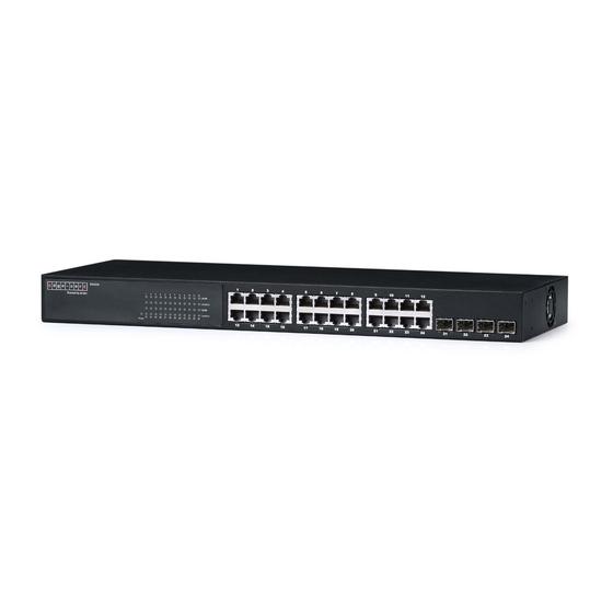
Chapter 1: Introduction Overview The ES4324 is an intelligent Layer 2 switch with 24 10/100/1000BASE-T ports, four of which are Gigabit combination ports that are shared with four SFP transceiver slots (see Figure 1-1, Ports 21-24). Port Status Indicators 10/100/1000 Mbps RJ-45 Ports... -
Page 18: Switch Architecture
Introduction Switch Architecture The switch employs a wire-speed, non-blocking switching fabric. This permits simultaneous wire-speed transport of multiple packets at low latency on all ports. The switch also features full-duplex capability on all ports, which effectively doubles the bandwidth of each connection. The switch uses store-and-forward switching to ensure maximum data integrity. -
Page 19: Port And Power Status Leds
Description of Hardware Port and Power Status LEDs The switch includes a display panel for key system and port indications that simplify installation and network troubleshooting. The LEDs, which are located on the front panel for easy viewing, are shown below and described in the following tables. Power Status LED Port Status LEDs Figure 1-3 Port and Power LEDs... -
Page 20: Power Supply Socket
Introduction Power Supply Socket The power socket is located on the rear panel of the switch. The standard power socket is for the AC power cord. 100-240V ~50-60Hz 0.8A Figure 1-4 Power Supply Socket Features and Benefits Connectivity • 24 10/100/1000 Mbps ports for easy Gigabit Ethernet integration and for protection of your investment in legacy LAN equipment. -
Page 21: Management
Features and Benefits Management • “At-a-glance” LEDs for easy troubleshooting. • Network management agent • Manages switch in-band • Supports SNMP v1/v2c, RMON and web-based interface... - Page 22 Introduction...
-
Page 23: Chapter 2: Network Planning
Chapter 2: Network Planning Introduction to Switching A network switch allows simultaneous transmission of multiple packets via non-crossbar switching. This means that it can partition a network more efficiently than bridges or routers. the switch have, therefore, been recognized as one of the most important building blocks for today’s networking technology. -
Page 24: Application Examples
Network Planning Application Examples The switch is not only designed to segment your network, but also to provide a wide range of options in setting up network connections. Some typical applications are described below. Collapsed Backbone The switch is an excellent choice for mixed Ethernet, Fast Ethernet, and Gigabit Ethernet installations where significant growth is expected in the near future. -
Page 25: Central Wiring Closet
Application Examples Central Wiring Closet With 24 parallel bridging ports (i.e., 24 distinct collision domains), this switch can collapse a complex network down into a single efficient bridged node, increasing overall bandwidth and throughput. In the figure below, the 1000BASE-T RJ-45 ports on the switch are providing 1 Gbps full-duplex connections for up to 24 local segments. -
Page 26: Remote Connections With Fiber Cable
Network Planning Remote Connections with Fiber Cable Fiber optic technology allows for longer cabling than any other media type. A 1000BASE-SX (MMF) link can connect to a site up to 550 meters away, a 1000BASE-LX (SMF) link up to 5 km, and a 1000BASE-LH link up to 70 km. This allows a switch stack to serve as a collapsed backbone, providing direct connectivity for a widespread LAN. -
Page 27: Making Vlan Connections
Application Examples Making VLAN Connections The switch supports VLANs that can be used to organize any group of network nodes into separate broadcast domains. VLANs confine broadcast traffic to the originating group, and can eliminate broadcast storms in large networks. This provides a more secure and cleaner network environment. -
Page 28: Application Notes
Network Planning Application Notes Full-duplex operation only applies to point-to-point access (such as when a switch is attached to a workstation, server or another switch). When the switch is connected to a hub, both devices must operate in half-duplex mode. For network applications that require routing between dissimilar network types, you can attach the switch directly to a multi-protocol router. -
Page 29: Chapter 3: Installing The Switch
Chapter 3: Installing the Switch Selecting a Site switch units can be mounted in a standard 19-inch equipment rack or on a flat surface. Be sure to follow the guidelines below when choosing a location. • The site should: • be at the center of all the devices you want to link and near a power outlet. •... -
Page 30: Equipment Checklist
Then, before beginning the installation, be sure you have all other necessary installation equipment. Package Contents • ES4324 switch • Four adhesive foot pads • Bracket Mounting Kit containing two brackets and eight screws for attaching the brackets to the switch •... -
Page 31: Mounting
Mounting Mounting A switch unit can be mounted in a standard 19-inch equipment rack or on a desktop or shelf. Mounting instructions for each type of site follow. Rack Mounting Before rack mounting the switch, pay particular attention to the following factors: •... -
Page 32: Desktop Or Shelf Mounting
Installing the Switch Mount the device in the rack, using four rack-mounting screws (not provided). Be sure to secure the lower rack-mounting screws first to prevent the brackets being bent by the weight of the switch. Figure 3-3 Installing the Switch in a Rack If installing a single switch only, turn to “Connecting to a Power Source”... -
Page 33: Installing An Optional Sfp Transceiver
Installing an Optional SFP Transceiver Set the device on a flat surface near an AC power source, making sure there are at least two inches of space on all sides for proper air flow. If installing a single switch only, go to “Connecting to a Power Source” at the end of this chapter. -
Page 34: Connecting To A Power Source
Installing the Switch Connecting to a Power Source To connect a device to a power source: Insert the power cable plug directly into the socket located at the back of the device. 100-240V ~50-60Hz 0.8A Figure 3-6 Power Socket Plug the other end of the cable into a grounded, three-pin, AC power source. Note: For international use, you may need to change the AC line cord. -
Page 35: Chapter 4: Making Network Connections
Chapter 4: Making Network Connections Connecting Network Devices The switch units are designed to interconnect multiple segments (or collision domains). It can be connected to network cards in PCs and servers, as well as to hubs, switches or routers. It may also be connected to devices using optional SFP transceivers. -
Page 36: Connecting To Pcs, Servers, Hubs And Switches
Making Network Connections Connecting to PCs, Servers, Hubs and Switches Attach one end of a twisted-pair cable segment to the device’s RJ-45 connector. Figure 4-1 Making Twisted-Pair Connections If the device is a PC card and the switch is in the wiring closet, attach the other end of the cable segment to a modular wall outlet that is connected to the wiring closet. -
Page 37: Network Wiring Connections
Twisted-Pair Devices Network Wiring Connections Today, the punch-down block is an integral part of many of the newer equipment racks. It is actually part of the patch panel. Instructions for making connections in the wiring closet with this type of equipment follows. Attach one end of a patch cable to an available port on the switch, and the other end to the patch panel. -
Page 38: Fiber Optic Sfp Devices
Making Network Connections Fiber Optic SFP Devices An optional Gigabit SFP transceiver (1000BASE-SX, 1000BASE-LX or 1000BASE-LH) can be used for a backbone connection between switches, or for connecting to a high-speed server. Each single-mode fiber port requires 9/125 micron single-mode fiber optic cable with an LC connector at both ends. -
Page 39: Figure 4-3 Making Connections To Sfp Transceivers
Fiber Optic SFP Devices Connect one end of the cable to the LC port on the switch and the other end to the LC port on the other device. Since LC connectors are keyed, the cable can be attached in only one orientation. Figure 4-3 Making Connections to SFP Transceivers As a connection is made, check the Link LED on the switch corresponding to the port to be sure that the connection is valid. -
Page 40: Connectivity Rules
Making Network Connections Connectivity Rules When adding hubs (repeaters) to your network, please follow the connectivity rules listed in the manuals for these products. However, note that because switches break up the path for connected devices into separate collision domains, you should not include the switch or connected cabling in your calculations for cascade length involving other devices. -
Page 41: 100 Mbps Fast Ethernet Collision Domain
Connectivity Rules 100 Mbps Fast Ethernet Collision Domain Table 4-5 Maximum Fast Ethernet Cable Length Type Cable Type Maximum Cable Length Connector 100BASE-TX Category 5 or better 100-ohm 100 m (328 ft) RJ-45 UTP or STP 10 Mbps Ethernet Collision Domain Table 4-6 Maximum Ethernet Cable Length Connector Type... -
Page 42: Cable Labeling And Connection Records
Making Network Connections Cable Labeling and Connection Records When planning a network installation, it is essential to label the opposing ends of cables and to record where each cable is connected. Doing so will enable you to easily locate inter-connected devices, isolate faults and change your topology without need for unnecessary time consumption. -
Page 43: Appendix A: Troubleshooting
Appendix A: Troubleshooting Diagnosing Switch Indicators Table A-1 Troubleshooting Chart Symptom Action Power LED is Off • Check connections between the switch, the power cord, and the wall outlet. • Contact your dealer for assistance. • Contact our Technical Support. Link LED is Off •... -
Page 44: Installation
Troubleshooting Installation Verify that all system components have been properly installed. If one or more components appear to be malfunctioning (such as the power cord or network cabling), test them in an alternate environment where you are sure that all the other components are functioning properly. -
Page 45: Appendix B: Cables
Appendix B: Cables Twisted-Pair Cable and Pin Assignments For 10BASE-T/100BASE-TX connections, a twisted-pair cable must have two pairs of wires. For 1000BASE-T connections the twisted-pair cable must have four pairs of wires. Each wire pair is identified by two different colors. For example, one wire might be green and the other, green with white stripes. -
Page 46: Straight-Through Wiring
Cables Table B-1 10/100BASE-TX MDI and MDI-X Port Pinouts MDI Signal Name MDI-X Signal Name Transmit Data plus (TD+) Receive Data plus (RD+) Transmit Data minus (TD-) Receive Data minus (RD-) Receive Data plus (RD+) Transmit Data plus (TD+) Receive Data minus (RD-) Transmit Data minus (TD-) 4,5,7,8 Not used... -
Page 47: Crossover Wiring
Twisted-Pair Cable and Pin Assignments Crossover Wiring If the twisted-pair cable is to join two ports and either both ports are labeled with an “X” (indicating MDI-X) or neither port is labeled with an “X” (which indicates MDI), a crossover must be implemented in the wiring. (When auto-negotiation is enabled for any RJ-45 port on the switch, you can use either straight-through or crossover cable to connect to any device type.) You must connect all four wire pairs as shown in the following diagram to support... -
Page 48: Cable Testing For Existing Category 5 Cable
Cables Table B-2 1000BASE-T MDI and MDI-X Port Pinouts MDI Signal Name MDI-X Signal Name Bi-directional Data Three Plus (BI_D3+) Bi-directional Data Four Plus (BI_D4+) Bi-directional Data Three Minus (BI_D3-) Bi-directional Data Four Minus (BI_D4-) Bi-directional Data Two Minus (BI_D2-) Bi-directional Data One Minus (BI_D1-) Bi-directional Data Four Plus (BI_D4+) Bi-directional Data Three Plus (BI_D3+) -
Page 49: Appendix C: Specifications
Appendix C: Specifications Physical Characteristics Ports 20 10/100/1000BASE-T, with auto-negotiation 4 10/100/1000BASE-T shared with 4 SFP transceiver slots. Network Interface Ports 1-24: RJ-45 connector, auto MDI/X 10BASE-T: RJ-45 (100-ohm, UTP cable; Category 3 or better) 100BASE-TX: RJ-45 (100-ohm, UTP cable; Category 5 or better) 1000BASE-T: RJ-45 (100-ohm, UTP or STP cable;... -
Page 50: Switch Features
Specifications AC Input 100 to 240 V, 50-60 Hz, 0.8 A Power Supply Internal, auto-ranging transformer: 100 to 240 VAC, 50 to 60 Hz Power Consumption 28 Watts maximum Maximum Current 0.25 A @ 115 VAC 0.12 A @ 230 VAC Switch Features Forwarding Mode Store-and-forward... -
Page 51: Compliances
Compliances Compliances CE Mark Emissions FCC Class A VCCI Class A Immunity EN 61000-4-2/3/4/5/6/8/11 Safety CSA 22.2.60950-1 & UL 60950-1 IEC 60950-1/ EN60950-1... - Page 52 Specifications...
-
Page 53: Glossary
Glossary 10BASE-T IEEE 802.3 specification for 10 Mbps Ethernet over two pairs of Category 3 or better UTP cable. 100BASE-TX IEEE 802.3u specification for 100 Mbps Fast Ethernet over two pairs of Category 5 or better UTP cable. 1000BASE-LH Specification for long-haul Gigabit Ethernet over two strands of 9/125 micron core fiber cable. - Page 54 Glossary CSMA/CD CSMA/CD (Carrier Sense Multiple Access/Collision Detect) is the communication method employed by Ethernet, Fast Ethernet, or Gigabit Ethernet. End Station A workstation, server, or other device that does not forward traffic. Ethernet A network communication system developed and standardized by DEC, Intel, and Xerox, using baseband transmission, CSMA/CD access, logical bus topology, and coaxial cable.
- Page 55 Glossary IEEE 802.3x Defines Ethernet frame start and stop requests and timers used for flow control on full-duplex links. (Now incorporated in IEEE 802.3-2005.) IEEE 802.3z Defines CSMA/CD access method and physical layer specifications for 1000BASE Gigabit Ethernet. (Now incorporated in IEEE 802.3-2005.) LAN Segment Separate LAN or collision domain.
- Page 56 Glossary Redundant Power Supply (RPS) A backup power supply unit that automatically takes over in case the primary power supply should fail. RJ-45 Connector A connector for twisted-pair wiring. Switched Ports Ports that are on separate collision domains or LAN segments. Telecommunications Industry Association Transmission Control Protocol/Internet Protocol (TCP/IP) Protocol suite that includes TCP as the primary transport protocol, and IP as the...
-
Page 57: Index
Index cooling problems A-1 Numerics cord sets, international 3-6 10 Mbps connectivity rules 4-7 100 Mbps connectivity rules 4-7 1000 Mbps connectivity rules 4-6 desktop mounting 3-4 1000BASE-LX fiber cable lengths 4-6 device connections 4-1 1000BASE-SX fiber cable lengths 4-6 1000BASE-T pin assignments B-3 electrical interference, avoiding 3-1... - Page 58 Index location requirements 3-1 status LEDs 1-3 surge suppressor, using 3-1 switch architecture 1-2 switching, introduction to 2-1 management agent 1-2 features 1-5, C-2, C-3 SNMP 1-2 temperature within a rack 3-3 mounting the switch troubleshooting in a rack 3-3 in-band access A-2 on a desktop or shelf 3-4 power and cooling problems A-1...
- Page 60 ES4324 E092007-AP-R01 150200057600A...
Need help?
Do you have a question about the ES4324 and is the answer not in the manual?
Questions and answers