Sign In
Upload
Download
Table of Contents
Contents
Add to my manuals
Delete from my manuals
Share
URL of this page:
HTML Link:
Bookmark this page
Add
Manual will be automatically added to "My Manuals"
Print this page
×
Bookmark added
×
Added to my manuals
Manuals
Brands
Edge-Core Manuals
Switch
ES4524D
Installation manual
Edge-Core ES4524D Installation Manual
24/48-port gigabit ethernet switch
Hide thumbs
Also See for ES4524D
:
Management manual
(588 pages)
1
2
3
4
5
6
7
8
9
10
11
12
Table Of Contents
13
14
15
16
17
18
19
20
21
22
23
24
25
26
27
28
29
30
31
32
33
34
35
36
37
38
39
40
41
42
43
44
45
46
47
48
49
50
51
52
53
54
55
56
57
58
59
60
61
62
63
64
page
of
64
Go
/
64
Contents
Table of Contents
Troubleshooting
Bookmarks
Table of Contents
Japan VCCI Class a
Power Cord Safety
Safety Compliance
Warnings and Cautionary Messages
Manufacturing Materials
Related Publications
Table of Contents
Chapter 1: Introduction
Overview
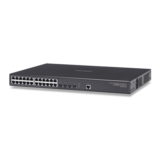
Figure 1-1 Front Panels
Figure 1-2 Rear Panel
Network Management Options
Switch Architecture
Description of Hardware
10/100/1000BASE-T Ports
SFP Slots
Port and System Status Leds
Table 1-1 Port Status Leds
Figure 1-3 Port Leds
Optional Redundant Power Supply
Power Supply Sockets
Table 1-2 System Status Leds
Figure 1-4 System Leds
Figure 1-5 Power Supply Sockets
Features and Benefits
Connectivity
Expandability
Performance
Management
Chapter 2: Network Planning
Introduction to Switching
Application Examples
Collapsed Backbone
Figure 2-1 Collapsed Backbone
Network Aggregation Plan
Figure 2-2 Network Aggregation Plan
Remote Connections with Fiber Cable
Figure 2-3 Remote Connections with Fiber Cable
Making VLAN Connections
Figure 2-4 Making VLAN Connections
Application Notes
Chapter 3: Installing the Switch
Selecting a Site
Ethernet Cabling
Equipment Checklist
Package Contents
Optional Rack-Mounting Equipment
Figure 3-1 RJ-45 Connections
Mounting
Rack Mounting
Figure 3-2 Attaching the Brackets
Desktop or Shelf Mounting
Figure 3-3 Installing the Switch in a Rack
Figure 3-4 Attaching the Adhesive Feet
Installing an Optional SFP Transceiver
Figure 3-5 Inserting an SFP Transceiver into a Slot
Connecting to a Power Source
Connecting to the Console Port
Figure 3-6 Power Socket
Figure 3-7 Serial Port (RJ-45) Pin-Out
Table 3-1 Serial Cable Wiring
Wiring Map for Serial Cable
Chapter 4: Making Network Connections
Connecting Network Devices
Twisted-Pair Devices
Cabling Guidelines
Connecting to Pcs, Servers, Hubs and Switches
Network Wiring Connections
Figure 4-1 Making Twisted-Pair Connections
Fiber Optic SFP Devices
Figure 4-2 Network Wiring Connections
Connectivity Rules
Figure 4-3 Making Connections to SFP Transceivers
100 Mbps Fast Ethernet Collision Domain
1000 Mbps Gigabit Ethernet Collision Domain
1000BASE-T Cable Requirements
Table 4-1 Maximum 1000BASE-T Gigabit Ethernet Cable Length
Table 4-2 Maximum 1000BASE-SX Gigabit Ethernet Cable Length
Table 4-3 Maximum 1000BASE-LX Gigabit Ethernet Cable Length
Table 4-4 Maximum 1000BASE-LH Gigabit Ethernet Cable Length
Table 4-5 Maximum Fast Ethernet Cable Length
10 Mbps Ethernet Collision Domain
Cable Labeling and Connection Records
Table 4-6 Maximum Ethernet Cable Length
Appendix A: Troubleshooting
Diagnosing Switch Indicators
Diagnosing Power Problems with the Leds
Power and Cooling Problems
Table A-1 Troubleshooting Chart
Table A-2 Power/Rps Leds
Installation
In-Band Access
Appendix B: Cables
Twisted-Pair Cable and Pin Assignments
10BASE-T/100BASE-TX Pin Assignments
Figure B-1 RJ-45 Connector Pin Numbers
Straight-Through Wiring
Crossover Wiring
Table B-1 10/100BASE-TX MDI and MDI-X Port Pinouts
Figure B-2 Straight-Through Wiring
1000BASE-T Pin Assignments
Table B-2 1000BASE-T MDI and MDI-X Port Pinouts
Figure B-3 Crossover Wiring
Cable Testing for Existing Category 5 Cable
Adjusting Existing Category 5 Cabling to Run 1000BASE-T
Fiber Standards
Appendix C: Specifications
Physical Characteristics
Switch Features
Management Features
Standards
Compliances
Appendix D: German Instructions
Eine Site Auswählen (Selecting a Site - German
Advertisement
Quick Links
1
Overview
2
Figure 1-1 Front Panels
3
Network Management Options
Download this manual
ES4524D
ES4548D
24/48-Port
Gigabit Ethernet Switch
Powered by Accton
Installation Guide
Installationsanleitung
Installationsanleitung
www.edge-core.com
Table of
Contents
Previous
Page
Next
Page
1
2
3
4
5
Advertisement
Table of Contents
Need help?
Do you have a question about the ES4524D and is the answer not in the manual?
Ask a question
Questions and answers
Related Manuals for Edge-Core ES4524D
Switch Edge-Core Direk Tronik 24/48-Port Management Manual
24/48-port gigabit ethernet switch powered by accton (588 pages)
Switch Edge-Core ES4324 Installation Manual
24-port gigabit ethernet lite switch (60 pages)
Switch Edge-Core ES4624-SFP Manual
L3 gigabit ethernet switch (932 pages)
Switch Edge-Core ES4624-SFP User Manual
L3 gigabit ethernet switch (24 pages)
Switch Edge-Core ES4650F Installation Manual
24/48-port stackable layer 3 gigabit ethernet switch (76 pages)
Switch Edge-Core ES4005V Installation Manual
5/8-port gigabit switch (20 pages)
Switch Edge-Core ES4512C Installation Manual
12/24/48-port gigabit intelligent switch (62 pages)
Switch Edge-Core ES4548D Installation Manual
24/48-port gigabit ethernet switch (64 pages)
Switch Edge-Core ES4626F Management Manual
24/48-port stackable layer 3 gigabit ethernet switch (792 pages)
Switch Edge-Core ES4528V-38 Management Manual
28-port gigabit ethernet switch (396 pages)
Switch Edge-Core ES4308-PoE Management Manual
Edge-core es4308-poe 8-port web-smart poe switch (74 pages)
Switch Edge-Core ES4308-POE Installation Manual
8-port web-managed poe switch (60 pages)
Switch Edge-Core ES4704BD User Manual
Es4700 series chassis core routing switch (93 pages)
Switch Edge-Core ES4524M-POE Installation Manual
L2/4 gigabit ethernet switch with power-over-ethernet (60 pages)
Switch Edge-Core ES4524M-PoE Management Manual
24-port layer 2/4 gigabit ethernet switch with poe (560 pages)
Switch Edge-Core ES3628EA User Manual
L3 24 10/100 ports + 4ge (802 pages)
This manual is also suitable for:
Es4548d
Table of Contents
Print
Rename the bookmark
Delete bookmark?
Delete from my manuals?
Login
Sign In
OR
Sign in with Facebook
Sign in with Google
Upload manual
Upload from disk
Upload from URL


Need help?
Do you have a question about the ES4524D and is the answer not in the manual?
Questions and answers