
Related Manuals for Edge-Core ES4308-PoE


Summary of Contents for Edge-Core ES4308-PoE
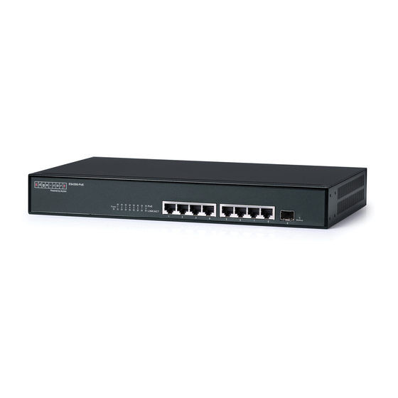
- Page 1 Powered by Accton ES4308-PoE 8-Port Web-Smart PoE Switch Management Guide www.edge-core.com...
- Page 3 Management Guide Web-Smart PoE Switch with 7 10/100/1000BASE-T (RJ-45) Ports and 1 Gigabit Combination (RJ-45/SFP) Port...
- Page 4 ES4308-PoE E022009/ST-R02 F2.00 149100036400A...
-
Page 5: About This Guide
The following publication details the hardware features of the switch, including the physical and performance-related characteristics, and how to install the switch: The ES4308-PoE Installation Guide Also, as part of the switch’s software, there is an online web-based help that describes all management related features. - Page 6 • Added the Ingress Filtering Enabled option to the VLAN Port Configuration screen (page 3-26). • Updated descriptive text under “802.1X” on page 3-28. • Added description of counters under “Displaying 802.1X Statistics” on page 3-30. • Added “RSTP” on page 3-35. •...
-
Page 7: Table Of Contents
Contents Chapter 1: Introduction Description of Software Features Chapter 2: Initial Configuration Chapter 3: Configuring the Switch Using the Web Interface Navigating the Web Browser Interface Home Page Configuration Options Panel Display Main Menu Web Configuration Displaying Status Overview Showing Port Statistics Displaying the System Name 3-10 Setting the Switch’s IP Address... - Page 8 Contents 802.1X 3-28 Configuring 802.1X 3-29 Displaying 802.1X Statistics 3-30 LLDP Settings 3-34 LLDP Neighbor Table 3-35 RSTP 3-35 Configuring RSTP 3-36 Displaying RSTP Status 3-40 QoS Settings 3-42 SNMP 3-47 3-48 Power over Ethernet Settings 3-49 Appendix A: Software Specifications Software Features Management Features Standards...
- Page 9 Tables Table 3-1 Web Page Configuration Buttons Table 3-2 Switch Main Menu Table 3-3 Port Statistics Table 3-3 Recommended STA Path Cost Range 3-38 Table 3-3 Default STA Path Costs 3-38 Table 3-4 Mapping CoS Values to Egress Queues 3-43...
- Page 10 Tables...
- Page 11 Figures Figure 3-1 Home Page Figure 3-2 Front Panel Indicators Figure 3-3 System Information Figure 3-4 Port Statistics Figure 3-5 System Name 3-10 Figure 3-6 LAN Settings 3-11 Figure 3-7 Password Settings 3-12 Figure 3-8 Reset to Factory Defaults 3-13 Figure 3-9 Upgrade Firmware 3-13...
- Page 12 Figures viii...
-
Page 13: Chapter 1: Introduction
Chapter 1: Introduction The ES4308-PoE is a web-managed Gigabit PoE switch that delivers performance and control to your network. It provides 8 full-duplex 1000BASE-T ports that significantly improve network performance and boost throughput using features configured through a web-based management interface. With 16 Gigabits of throughput bandwidth, this switch provides an effective solution to meeting the growing demands on your network. - Page 14 Introduction of broadcast traffic passing through the port is restricted. If broadcast traffic rises above a pre-defined threshold, it will be throttled until the level falls back beneath the threshold. Static Addresses – A static address can be assigned to a specific interface on this switch.
- Page 15 Description of Software Features • Provide data security by restricting all traffic to the originating VLAN. Traffic Prioritization – This switch prioritizes each packet based on the required level of service, using four priority queues with Weighted Round Robin Queuing. It uses IEEE 802.1p and 802.1Q tags to prioritize incoming traffic based on input from the end-station application.
- Page 16 Introduction...
-
Page 17: Chapter 2: Initial Configuration
Chapter 2: Initial Configuration To make use of the management features of your ES4308-PoE, you must first configure it with an IP address that is compatible with the network in which it is being installed. This should be done before you permanently install the switch in the network. - Page 18 Initial Configuration...
-
Page 19: Chapter 3: Configuring The Switch
Chapter 3: Configuring the Switch Using the Web Interface This switch provides an embedded HTTP web agent. Using a web browser you can configure the switch and view statistics to monitor network activity. The web agent can be accessed by any computer on the network using a standard web browser (Internet Explorer 5.5 or above, or Mozilla Firefox 1.0 or above). -
Page 20: Home Page
Configuring the Switch Home Page When your web browser connects with the switch’s web agent, the home page is displayed as shown below. The home page displays the Main Menu on the left side of the screen and System Information on the right side. The Main Menu links are used to navigate to other menus, and display configuration parameters and statistics. -
Page 21: Configuration Options
Navigating the Web Browser Interface Configuration Options Configurable parameters have a dialog box or a drop-down list. Once a configuration change has been made on a page, be sure to click on the Apply button to confirm the new setting. The following table summarizes the web page configuration buttons. -
Page 22: Main Menu
Configuring the Switch Main Menu Using the onboard web agent, you can define system parameters, manage and control the switch, and all its ports, or monitor network conditions. The following table briefly describes the selections available from the web-browser interface. Table 3-2 Switch Main Menu Menu Description... - Page 23 Navigating the Web Browser Interface Table 3-2 Switch Main Menu (Continued) Menu Description Page VLANS 3-24 VLAN Membership Configure VLAN port groups. 3-24 VLAN Port Config Configures VLAN behavior for individual ports and 3-26 trunks. 802.1X 3-28 Settings Sets up 802.1X port authentication. 3-29 Statistics Displays the 802.1X statistics collected by the switch.
-
Page 24: Web Configuration
Configuring the Switch Web Configuration Displaying Status Overview You can easily identify the system by displaying the device name, location and contact information. Field Attributes System Information • System Name – Name assigned to the switch system. • System Location – Specifies the system location. •... - Page 25 Web Configuration • Flow Control Status – Indicates whether flow control is enabled or disabled. (IEEE 802.3x, or Back-Pressure) • Auto-negotiation – Shows if auto-negotiation is enabled or disabled. • Frame Type – Either “Tagged” or “All.” “Tagged” means that the port will only receive VLAN-tagged frames.
-
Page 26: Figure 3-3 System Information
Configuring the Switch Web – Click STATUS, Overview. Figure 3-3 System Information... -
Page 27: Showing Port Statistics
Web Configuration Showing Port Statistics You can display statistics on network traffic from the ports. These statistics can be used to identify potential problems with the switch (such as a faulty port or unusually heavy loading). All values displayed have been accumulated since the last system reboot, but can be reset to zero by clicking the CLEAR button. -
Page 28: Displaying The System Name
Configuring the Switch Displaying the System Name You can easily identify the system by displaying the device name and other descriptive information. Field Attributes • Switch Name – A name assigned to the switch system. • System Location – Specifies the system location. •... -
Page 29: Manual Configuration
Web Configuration Note: If you cannot remember the switch’s IP address, you can restore the original settings by following the procedure described in the “Troubleshooting” section. Manual Configuration Web – Click SYSTEM, LAN Settings. Enter the IP address, subnet mask and gateway, then click APPLY. -
Page 30: Configuring The Logon Password
Configuring the Switch Configuring the Logon Password The administrator has write access for all parameters governing the onboard agent. You should therefore assign a new administrator password as soon as possible, and store it in a safe place. Field Attributes Password –... -
Page 31: Tools
Click the APPLY button to upgrade the selected switch firmware file. You can download firmware files for your switch from the Support section of the Edgecore web site at www.edge-core.com. Web – Click System, Tools, Reset to Factory Defaults. -
Page 32: Upload/Download Configuration
Configuring the Switch Upload/Download Configuration Web – Click SYSTEM, Tools, Upload/Download Configuration. To upload or download the configuration file, select “Upload/Download Configuration” from the Tools drop-down list, then click “Upload” or “Download,” and then click on the “Browse” button to select the file. Then click the APPLY button to transfer the switch configuration file. -
Page 33: Register Product
Web Configuration Register Product Edgecore requests that you register your switch online, if you have not already done so. The Register Product page provides a convenient link to the Edgecore web site for this purpose. Web – Click System, Register Product. Click the Register Now button to access the Edgecore web site and register your switch. -
Page 34: Figure 3-13 Port Configuration
Configuring the Switch Web – Click PORTS, Settings. Enable or disable jumbo frames, select the required settings for any port, and then click APPLY. Figure 3-13 Port Configuration 3-16... -
Page 35: Storm Control
Web Configuration Storm Control Broadcast storms may occur when a device on your network is malfunctioning, or if application programs are not well designed or properly configured. If there is too much broadcast traffic on your network, performance can be severely degraded or everything can come to complete halt. -
Page 36: Port Mirroring
Configuring the Switch Port Mirroring You can mirror traffic from any source port to a target port for real-time analysis. You can then attach a logic analyzer or RMON probe to the target port and study the traffic crossing the source port in a completely unobtrusive manner. Field Attributes •... -
Page 37: Cable Diagnostic
Web Configuration Cable Diagnostic You can perform cable diagnostics for all ports or selected ports to diagnose any cable faults (short, open etc.) and feedback a distance to the fault. Field Attributes • Cable Diagnostics – Cable diagnostics is performed on a per-port basis. Select the port number from the drop-down list. -
Page 38: Trunk Membership
Configuring the Switch Trunk Membership You can create multiple links between devices that work as one virtual, aggregate link. A port trunk offers a dramatic increase in bandwidth for network segments where bottlenecks exist, as well as providing a fault-tolerant link between two devices. -
Page 39: Trunk Configuration
Web Configuration Trunk Configuration This page allows you to configure the speed, duplex mode, and flow control for a trunk. Field Attributes • Trunk – Indicates trunk identification. • – Allows you to manually set the port speed and duplex mode for Speed/Duplex all ports in the trunk. -
Page 40: Figure 3-19 Lacp Port Configuration
Configuring the Switch Field Attributes • Port – The port number. • Enabled – Enables LACP on the associated port. • Key Value – Configures a port's LACP administration key. The port administrative key must be set to the same value for ports that belong to the same link aggregation group (LAG). -
Page 41: Lacp Status
Web Configuration LACP Status This page allows you display the operational state for the local and remote side of an link aggregation. Field Attributes Aggregation Information • Aggregation Group - Identifier for a local link aggregation group. • Partner MAC Address - Physical address of device at other end of link. •... -
Page 42: Configuring Vlan Groups
Configuring the Switch Configuring VLAN Groups The 802.1Q VLAN Configuration page allows you to create and delete VLANs (Virtual LANs), and set up or modify VLAN group members. Introduction to VLANs VLANs are logical partitions of the physical LAN. You can use VLANs to increase network performance or improve internal network security. -
Page 43: Figure 3-21 Vlan Settings
Web Configuration Web – Click VLANS, VLAN Membership. Create a new VLAN by giving it an ID (Range: 1~4094) and then clicking Add. Modify or delete a VLAN by selecting its radio button and clicking Modify or Delete. Figure 3-21 VLAN Settings 3-25... -
Page 44: Configuring Vlan Members
Configuring the Switch Configuring VLAN Members After creating a new VLAN, configure port and trunk members. Field Attributes • Port – Adds a port to the newly created VLAN. • Trunk – Adds a static trunk to the newly created VLAN. •... -
Page 45: Figure 3-23 Vlan Settings
Web Configuration VLAN aware ports will strip the VLAN tag from received frames and insert the tag in transmitted frames (except for the PVID). VLAN unaware ports will not strip the tag from received frames or insert the tag in transmitted frames. •... -
Page 46: 802.1X
Configuring the Switch 802.1X Network switches can provide open and easy access to network resources by simply attaching a client PC. Although this automatic configuration and access is a desirable feature, it also allows unauthorized personnel to easily intrude and possibly gain access to sensitive network data. -
Page 47: Configuring 802.1X
Web Configuration Configuring 802.1X Use the 802.1X Configuration page to specify global or port-specific parameters for the IEEE 802.1X Port Authentication Protocol. Field Attributes System Setting • Mode - Enables or disables 802.1X globally for all ports on the switch. The 802.1X protocol must be enabled globally for the switch before the port settings are active. -
Page 48: Displaying 802.1X Statistics
Configuring the Switch If a re-authentication fails, the IEEE802.1X standard enforces a so-called “quiet-period” in which the authenticator (switch) shall be quiet and not re-try another authentication – also packets from the supplicant are discarded during this quiet period – this way 'brute-force' attacks are prevented. Web –... - Page 49 Web Configuration • AuthTimeoutsWhileAuthenticating – The number of times that the state machine transitions from AUTHENTICATING to ABORTING, as a result of the Backend Authentication state machine indicating authentication timeout. • AuthEapStartsWhileAuthenticating – the number of times that the state machine transitions from AUTHENTICATING to ABORTING, as a result of an EAPOL-Start message being received from the Supplicant.
- Page 50 Configuring the Switch • backendAuthSuccesses – The number of times that the state machine receives an EAP-Success message from the Authentication Server. Indicates that the Supplicant has successfully authenticated to the Authentication Server. Dot1x MIB Counters • EapolFramesRx – The number of valid EAPOL frames of any type that have been received by this Authenticator.
-
Page 51: Figure 3-25 802.1X Statistics
Web Configuration Web – Click 802.1X, Statistics. Figure 3-25 802.1X Statistics 3-33... -
Page 52: Lldp Settings
Configuring the Switch LLDP Settings This page allows you to configure the Link Layer Discovery Protocol (LLDP). LLDP allows devices in the local broadcast domain to share information about themselves. LLDP-capable devices periodically transmit information in messages called Type Length Value (TLV) fields to neighbor devices. Advertised information is represented in Type Length Value (TLV) format according to the IEEE 802.1ab standard, and can include details such as device identification, capabilities and configuration settings. -
Page 53: Lldp Neighbor Table
Web Configuration LLDP Neighbor Table This page provides information on neighboring devices. Field Attributes • Local Port - The local port to which a remote LLDP-capable device is attached. • Chassis ID - An identifier for the particular chassis in this system. In most cases, this is the MAC address of the remote device. -
Page 54: Configuring Rstp
Configuring the Switch the lowest cost spanning tree, it enables all root ports and designated ports, and disables all other ports. Network packets are therefore only forwarded between root ports and designated ports, eliminating any possible network loops. Once a stable network topology has been established, all bridges listen for Hello BPDUs (Bridge Protocol Data Units) transmitted from the Root Bridge. - Page 55 Web Configuration • Forward Delay – The maximum time (in seconds) this device will wait before changing states (i.e., discarding to learning to forwarding). This delay is required because every device must receive information about topology changes before it starts to forward frames. In addition, each port needs time to listen for conflicting information that would make it return to a discarding state;...
-
Page 56: Table 3-3 Recommended Sta Path Cost Range
Configuring the Switch Note that when Force Version is set to Compatible mode (STP) and the default path cost recommended by the IEEE 8021w standard exceeds 65,535, the default is set to 65,535. Table 3-3 Recommended STA Path Cost Range Port Type IEEE 802.1D-1998 IEEE 802.1w-2001... -
Page 57: Figure 3-28 Rstp Configuration
Web Configuration Web – Click RSTP, Settings. Set any required system or port-specific attributes for RSTP, and click APPLY. Figure 3-28 RSTP Configuration 3-39... -
Page 58: Displaying Rstp Status
Configuring the Switch Displaying RSTP Status Use the RSTP Status page to display global and port-specific status and attribute settings for the Rapid Spanning Tree Protocol. Field Attributes RSTP Bridge Overview • Hello Time – Interval (in seconds) at which the root device transmits a configuration message. -
Page 59: Figure 3-29 Rstp Configuration
Web Configuration • Port Role – Roles are assigned according to whether the port is part of the active topology connecting the bridge to the root bridge (i.e., root port), connecting a LAN through the bridge to the root bridge (i.e., designated port); or is an alternate or backup port that may provide connectivity if other bridges, bridge ports, or LANs fail or are removed. -
Page 60: Qos Settings
Configuring the Switch QoS Settings QoS (Quality of Service) is a mechanism that is used to prioritize traffic as it is forwarded through the switch. Both the queue service mode (strict or weighted round robin), and the method of classifying the priority of ingress traffic can be configured on this page. -
Page 61: Table 3-4 Mapping Cos Values To Egress Queues
Web Configuration Field Attributes Queue Mode • Strict – Services the egress queues in sequential order, transmitting all traffic in the higher priority queues before servicing lower priority queues. • WRR – Weighted Round-Robin shares bandwidth at the egress ports by using scheduling weights with default values of 1, 2, 4, 8 for queues 0 through 7, respectively. -
Page 62: Figure 3-30 Port-Based Qos Settings
Configuring the Switch Web – Click QOS, Settings. In QoS Mode, select Port-based, 802.1p, or DSCP to configure the related parameters. When the QoS Mode is set to Port-based, the following table is displayed. Figure 3-30 Port-based QoS Settings When the QoS Mode is set to 802.1p, the 802.p Configuration table is displayed as shown below. -
Page 63: Figure 3-32 Dscp Configuration
Web Configuration When the QoS Mode is set to DSCP, the DSCP Configuration table is displayed as shown below. Figure 3-32 DSCP Configuration 3-45... -
Page 64: Snmp
Configuring the Switch SNMP Use the SNMP Settings page to configure the Simple Network Management Protocol (SNMP), including enabling the local SNMP agent on this switch, specifying a trap manager, and setting the access strings. Simple Network Management Protocol (SNMP) is a communication protocol designed specifically for managing devices on a network. -
Page 65: Poe
Web Configuration The switch can provide DC power to a wide range of connected devices, eliminating the need for an additional power source and cutting down on the amount of cables attached to each device. Once configured to supply power, an automatic detection process is initialized by the switch that is authenticated by a PoE signature from the connected device. -
Page 66: Power Over Ethernet Settings
Configuring the Switch Power over Ethernet Settings Configures Power over Ethernet (PoE) parameters for the switch. Field Attributes • Port 1 Power Mode – Port 1 may be configured to supply as much as 25 watts of power when set to High mode. In normal mode it can supply a maximum of 15.4 watts. -
Page 67: Appendix A: Software Specifications
Appendix A: Software Specifications Software Features Authentication RADIUS, Port (802.1X), Port Security DHCP Client Port Configuration 100BASE-TX: 10/100 Mbps, half/full duplex 1000BASE-T: 10/100 Mbps at half/full duplex, 1000 Mbps at full duplex Flow Control Full Duplex: IEEE 802.3-2005 Half Duplex: Back pressure Broadcast Storm Control Traffic throttled above a critical threshold Port Mirroring... -
Page 68: Management Features
Software Specifications Class of Service Supports two levels of priority (which can be configured by VLAN tag or port), Layer 3/4 priority mapping: IP DSCP Additional Features SNMP (Simple Network Management Protocol) Management Features In-Band Management Web-based HTTP, SNMP manager Software Loading HTTP in-band SNMP... -
Page 69: Management Information Bases
Management Information Bases Management Information Bases Bridge MIB (RFC 1493) Entity MIB (RFC 2737) Ether-like MIB (RFC 3635) Extended Bridge MIB (RFC 2674) Extensible SNMP Agents MIB (RFC 2742) Forwarding Table MIB (RFC 2096) Interface Group MIB (RFC 2233) Interfaces Evolution MIB (RFC 2863) MAU MIB (RFC 3636) MIB II (RFC 1213) Port Access Entity MIB (IEEE 802.1X) - Page 70 Software Specifications...
-
Page 71: Appendix B: Troubleshooting
Appendix B: Troubleshooting Forgot or Lost Password If you have forgotten the administration password you can return the switch to its factory default state by following these steps: Remove the power cord from the back of the switch. Remove all cables from the front-panel ports. Connect port 1 to port 2 on the front panel, using a standard network cable. - Page 72 Troubleshooting In the list of components used by this connection on the General tab, select Internet Protocol (TCP/IP), and then click the Properties button. In the Internet Protocol (TCP/IP) Properties dialog box, click to select Use the following IP address. Then type your intended IP address, Subnet mask, and Default gateway in the provided text boxes Click OK to save the changes.
- Page 74 ES4308-PoE E022009/ST-R02 149100036400A...