Table of Contents
Advertisement
Quick Links
Installer: Leave this manual with the appli-
ance.
Consumer: Retain this manual for future refer-
ence.
WARNING: If not installed, operated and main-
tained in accordance with the manufacturer's
instructions, this product could expose you
to substances in fuel or from fuel combustion
which can cause death or serious illness.
INSTALLATION INSTRUCTIONS
OWNER'S MANUAL
AND
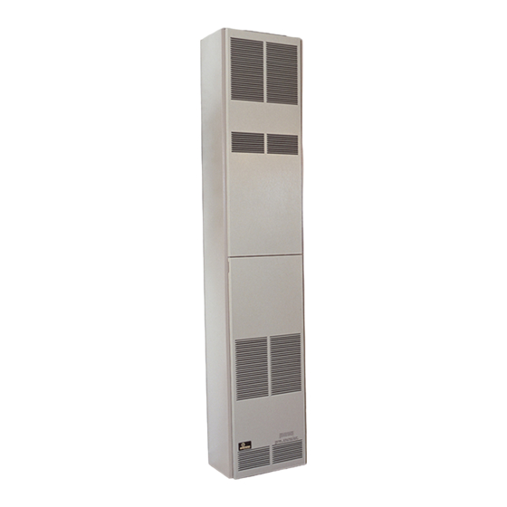
FAN TYPE
VENTED
WALL FURNACE
MODEL
FAW-55IP
WARNING: If the information in these in-
structions are not followed exactly, a fire or ex-
plosion may result causing property damage,
personal injury or loss of life.
— Do not store or use gasoline or other flamma-
ble vapors and liquids in the vicinity of this or
any other appliance.
— WHAT TO DO IF YOU SMELL GAS
•
Do not try to light any appliance.
•
Do not touch any electrical switch; do not
use any phone in your building.
•
Immediately call your gas supplier from a
neighbor's phone. Follow the gas suppli-
er's instructions.
•
If you cannot reach your gas supplier, call
the fire department.
— Installation and service must be performed
by a qualified installer, service agency or the
gas supplier.
Page 1
Advertisement
Table of Contents
Troubleshooting

Subscribe to Our Youtube Channel
Related Manuals for Empire Heating Systems FAN TYPE VENTED WALL FURNACE FAW-55IP


Summary of Contents for Empire Heating Systems FAN TYPE VENTED WALL FURNACE FAW-55IP
-
Page 1: Installation Instructions
INSTALLATION INSTRUCTIONS OWNER’S MANUAL FAN TYPE VENTED WALL FURNACE MODEL FAW-55IP WARNING: If the information in these in- structions are not followed exactly, a fire or ex- plosion may result causing property damage, personal injury or loss of life. — Do not store or use gasoline or other flamma- ble vapors and liquids in the vicinity of this or any other appliance. -
Page 2: Table Of Contents
TABLE OF CONTENTS SECTION PAGE INTRODUCTION ........................3 SAFETY INFORMATION FOR USERS OF LP-GAS ............4 INSTALLATION ........................ 5-9 LIGHTING INSTRUCTIONS .....................10 SERVICE AND MAINTENANCE SUGGESTIONS ........... 11-12 TROUBLESHOOTING .......................13 S8600H TROUBLESHOOTING GUIDE ..............14-15 PARTS LIST .........................16 PARTS VIEW ........................17 VENTING ..........................18 SERVICE NOTES ........................19 Page 2 12429-10-0408... -
Page 3: Introduction
INTRODUCTION Introduction Notice: During initial firing of this unit, its paint will bake out and Always consult your local Building Department regarding smoke will occur. To prevent triggering of smoke alarms, ventilate regulations, codes or ordinances which apply to the installation of the room in which the unit is installed. -
Page 4: Safety Information For Users Of Lp-Gas
SAFETY INFORMATION FOR USERS OF LP-GAS Propane (LP-Gas) is a flammable gas which can cause fires by point with the members of your household. Someday and explosions. In its natural state, propane is odorless and when there may not be a minute to lose, everyone’s safety colorless. -
Page 5: Installation
INSTALLATION Ventilation and Combustion Air 2. This furnace must not be connected to a chimney flue serving Wall furnaces shall be installed in a location in which the facilities a separate solid-fuel burning appliance. 3. Uninsulated Single-Wall Metal Pipe shall not be used for ventilation permit satisfactory combustion of gas and proper outdoors in cold climates for venting gas utilization venting under normal conditions. - Page 6 INSTALLATION Installing Optional Rear Outlet 4”(102mm) OVAL TYPE “B” Rear outlet kit, 10” (254mm) boot assembly with register, ROK-1 VENT CENTER TO COMBUSTIBLES CONNECTION MINIMUM CLEARANCE 9/16” (40mm) for warm air discharge into an adjoining room. 7/1/2” (191mm) MINIMUM CLEARANCE TOP TO COMBUSTIBLES Attention: Before furnace is attached to the wall, the wall opening for the rear outlet must be cut, in addition to removal of the outer...
- Page 7 INSTALLATION Locating Furnace On Wall Compounds used on threaded joints of gas piping shall be resistant to The furnace is to be located on a wall. The furnace is 16 inches the action of liquefied petroleum gases. The gas lines must be checked (406mm) in width and normal 16 inches (406mm) on center studs for leaks by the installer.
- Page 8 INSTALLATION Checking Manifold Pressure Both Propane and Natural gas valves have a built-in pressure regulator in the gas valve. Natural gas models will have a manifold pressure of approximately 3.5” w.c. (.871kPa) at the valve outlet with the inlet pressure to the valve from a minimum of 5.0” w.c. (1.24kPa) for the purpose of input adjustment to a maximum of 10.5”...
- Page 9 INSTALLATION Vent Safety Shutoff System Wiring This appliance must be properly connected to a venting system. This The appliance, when installed, must be electrically grounded in appliance is equipped with a vent safety shutoff system. accordance with local codes or, in the absence of local codes, with Warning: Operation of this wall furnace when not connected the National Electrical Code, ANSI/NFPA 70 or Canadian Electrical to a properly installed and maintained venting system or...
-
Page 10: Lighting Instructions
LIGHTING INSTRUCTIONS FOR YOUR SAFETY READ BEFORE OPERATING WARNING: If you do not follow these instructions exactly, a fire or explosion may result causing property damage, personal injury or loss of life. A. This appliance is equipped with an ignition device which •... -
Page 11: Service And Maintenance Suggestions
SERVICE AND MAINTENANCE SUGGESTIONS CALL SERVICEMAN GENERAL: All furnaces have been fire-tested to check for proper STEP 1: Perform Visual Inspection. operation. This includes, main burner flame, pilot flame, fan operation, A. With power off, make sure all wiring connections are clean and fan control, limit control and automatic valve operation. - Page 12 SERVICE AND MAINTENANCE SUGGESTIONS If the pilot does not light, or the pilot flame current is not at least Main Burner Operation 1.0 uA and steady, the module will not energize the second main When the pilot flame is established, a flame rectification circuit valve and the main burner will not light.
-
Page 13: Troubleshooting
TROUBLESHOOTING Important WARNING 1. The following service procedures are provided as a general When performing the following steps, do not touch stripped guide. end of jumper or SPARK terminal. The ignition circuit 2. Meter readings between gas control and ignition module must generates 13,000 volts at 25 pf load and electrical shock be taken within the trial for ignition period. -
Page 14: S8600H Troubleshooting Guide
S8600H TROUBLESHOOTING GUIDE Page 14 12429-10-0408... - Page 15 S8600H TROUBLESHOOTING GUIDE Green LED Status Codes Green LED Flash Code (X + Y) Indicates Next System Action Recommended Service Action No “Call for Heat” Not applicable None Flash Fast Startup-Flame sense calibration Not applicable None Heart Beat Normal operation Not applicable None Recycle...
-
Page 16: Parts List
PARTS LIST PLEASE NOTE: When ordering parts, it is very important that part number and description of part coincide. Index Part Index Part Number Description Number Description WFA-115 Baseplate Gasket DV-847 Burner Door Natural Gas 11763 Outer Casing Top DV-972 Burner Door LP Gas 632024 Motor Mount (Four Required) -
Page 17: Parts View
PARTS VIEW Empire Comfort Systems, Inc. Nine Eighteen Freeburg Ave. Belleville, Illinois 62222-0529 12429-10-0408 Page 17... -
Page 18: Venting
VENTING Model No. FAW-55 may be vented as shown. The vent cap must Use U.L. listed gas vent equipment when installing the FAW-55. be at least 12 feet (3.7m) above the floor. Clearance to combustible For vent pipe running through walls, roof, and within one inch construction is held by the fixed spacers at 1 inch (25mm) with B-1 (25mm) of combustible construction, use B-1 (one inch (25mm) vent pipe. -
Page 19: Service Notes
SERVICE NOTES 12429-10-0408 Page 19... - Page 20 Empire Comfort Systems Inc. EMPIRE EMPIRE 918 Freeburg Ave. Belleville, IL 62220 If you have a general question about our products, please e-mail us at info@empirecomfort.com. If you have a service or repair question, please contact your dealer. Comfort Systems www.empirecomfort.com Page 20 12429-10-0408...
Need help?
Do you have a question about the FAN TYPE VENTED WALL FURNACE FAW-55IP and is the answer not in the manual?
Questions and answers