Table of Contents
Advertisement
Installer: Please leave these instructions with
the consumer.
Consumer: Please retain these instructions
for future use.
WARNING: If not installed, operated and
maintained in accordance with the manu-
facturer's instructions, this product could
expose you to substances in fuel or from
fuel combustion which can cause death or
serious illness.
12426-4-0104
INSTALLATION INSTRUCTIONS
OWNER'S MANUAL
AND
GRAVITY VENTED
DUAL WALL FURNACE
MODEL
GWT-50-2 (SG, RB)
EFFECTIVE DATE
JANUARY 2004
WARNING: If the information in this
manual is not followed exactly, a Þ re or
explosion may result causing property
damage, personal injury or loss of life.
— Do not store or use gasoline or other ß am-
mable vapors and liquids in the vicinity
of this or any other appliance.
— WHAT TO DO IF YOU SMELL GAS
•
Do not try to light any appliance.
•
Do not touch any electrical switch; do
not use any phone in your building.
•
Immediately call your gas supplier
from a neighbor's phone. Follow the
gas supplier's instructions.
•
If you cannot reach your gas supplier,
call the Þ re department.
— Installation and service must be per-
formed by a qualiÞ ed installer, service
agency or the gas supplier.
Page 1
Advertisement
Table of Contents

Related Manuals for Empire Heating Systems GWT-50-2


Summary of Contents for Empire Heating Systems GWT-50-2
-
Page 1: Installation Instructions
— Installation and service must be per- formed by a qualiÞ ed installer, service agency or the gas supplier. GRAVITY VENTED MODEL GWT-50-2 (SG, RB) EFFECTIVE DATE JANUARY 2004 Do not try to light any appliance. Do not touch any electrical switch; do not use any phone in your building. -
Page 2: Table Of Contents
TABLE OF CONTENTS SECTION PAGE Important Safety Information ...3 Safety Information for Users of LP Gas ...4 Introduction ...5 SpeciÞ cations ...5 Recommended Vent ConÞ guration ...6 Gas Supply ...7 Clearances ...8 Ventilation and Combustion Air ...8 Location - All Models ...8 Rough-In Instructions ... -
Page 3: Important Safety Information
• This furnace must not be connected to a chimney ß ue serving a separate solid-fuel burning appliance. Page 3... -
Page 4: Safety Information For Users Of Lp Gas
SAFETY INFORMATION FOR USERS OF LP-GAS Propane (LP-Gas) is a ß ammable gas which can cause Þ res and explosions. In its natural state, propane is odorless and colorless. You may not know all the following safety precau- tions which can protect both you and your family from an accident. -
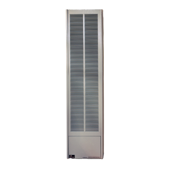
Page 5: Introduction
Gas Inlet Pipe Vent Pipe Type B Oval Accessory Blower Package GWT-50 (SG, RB) is a DUAL WALL Furnace. Warmed air is discharged into two rooms which share a common wall. 12426-4-0104 INTRODUCTION Gas utilization equipment in residential garages shall be installed so that all burners and burner ignition devices are located not less than 18"... -
Page 6: Recommended Vent Configuration
The cold vent pipe will have a delay in proper venting and cause the wall furnace to shut "off" by the vent safety switch. To prevent delayed venting as well as condensation of ß ue products an insulated vent enclosure is recommended. -
Page 7: Gas Supply
Check all local codes for requirements, especially for the size and type of gas supply line required. Recommended Gas Pipe Diameter Pipe Length Schedule 40 Pipe (Feet) Inside Diameter Nat. L.P. 0-10 1/2" 3/8" 1.3 cm 1.0 cm 10-40 1/2" 1/2"... -
Page 8: Clearances
Do not install in a closet, alcove or small hallway where the furnace ROUGH-IN INSTRUCTIONS Provide an opening in the wall 14 1/2" (368mm) wide and 66 1/8"... -
Page 9: Finishing Instructions
Plastering (Figure 4) In new construction use only plain (not perforated) gypsum lath around furnace and vent pipe so that plaster "Keys" will not project into wall space. Use wood strips nailed to inside of studs and top of bottom plate. - Page 10 FINISHING INSTRUCTIONS (continued) IMPORTANT — Avoid securing too tightly and disturbing the inner casing. Do not try to force furnace into a wall opening which is smaller than speciÞ ed dimension. OUTER CASING (Figure 6) 1. Align 1 3/4" slot on casing bracket with bottom screw hole on inner casing.
-
Page 11: Thermostat Location (Sg Models)
They should never be used on line or low voltage A.C. circuits. Interior Wall — The thermostat should be installed on an inside wall away from the furnace but in the same room. Note: Use 16 gauge wire to prevent excessive loss of milli- volts. -
Page 12: To Turn Off Gas
LIGHTING INSTRUCTIONS FOR YOUR SAFETY READ BEFORE LIGHTING WARNING: If you do not follow these instructions exactly, a Þ re or explosion may result causing property damage, personal injury or loss of life. A. This appliance has a pilot which must be lighted by hand. -
Page 13: Vent Safety Shutoff System
ß ame. The burner does not have a primary air adjustment. The ß ame will be proper if the factory-set pressure and oriÞ ce are used. After the furnace has begun operating, cleaning of the burner may be needed for proper ß ame, examine at least 2 times per season. -
Page 14: Troubleshooting
Pilot Does Not Light With air in the gas line, such as when the furnace is Þ rst installed or was "OFF" all summer, the pilot ß ame may be too lean to ignite on the Þ rst few trials. Turn the gas control knob to PILOT position and depress the gas control knob. -
Page 15: Parts List
Do not order bolts, screws, washers or nuts. They are standard hardware items and can be purchased at any local hardware store. Shipments contingent upon strikes, Þ res and all causes beyond our control. Empire Comfort Systems, Inc. Nine Eighteen Freeburg Ave. Belleville, Illinois 62222-0529 12426-4-0104... -
Page 16: Parts View
PARTS VIEW Page 16 12426-4-0104... -
Page 17: Remote Bulb Control Installation Instructions
1. Remove remote bulb control from the shipping carton. 2. Remove outer casing assembly from shipping carton. Note: If wall furnace is already installed, remove outer casing from unit and lay on ß oor with front side down. 3. Attach wire assembly to remote bulb control. -
Page 18: Optional Blower Installation Instructions
OPTIONAL BLOWER INSTALLATION INSTRUCTIONS GWT-25 (SG, RB), GWT-35 (SG, RB), GWT-50 (SG, RB) Installing Blower Using Three-Prong Plug 1. Install furnace according to Installation Instructions and Owner's Manual. 2. Refer to Drawing for measurements to locate (2) mounting holes on wall surface above furnace. - Page 19 Figure 3 Fan Control The automatic fan control is located on the bottom of the blower assembly. The fan control is a nonadjustable, automatic type. The fan control will require between 3 and 7 minutes of main burner operation before the fan control "closes"...
-
Page 20: Service Notes
Empire Comfort Systems, Inc. Nine Eighteen Freeburg Ave. Belleville, Illinois 62220-2623 Page 20 SERVICE NOTES E-MAIL: info@empirecomfort.com WEB SITE: www.empirecomfort.com PH: 1-618-233-7420 PH: 1-800-851-3153 FAX: 1-618-233-7097 FAX: 1-800-443-8648 12426-4-0104...
Need help?
Do you have a question about the GWT-50-2 and is the answer not in the manual?
Questions and answers