Table of Contents
Advertisement
Quick Links
Advertisement
Table of Contents

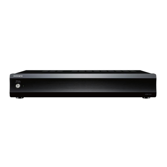
Summary of Contents for Integra ADM-30.1
- Page 1 2 Channel Amplifier ADM-30.1 Instruction Manual...
-
Page 2: Important Safety Instructions
WARNING: WARNING AVIS RISK OF ELECTRIC SHOCK RISQUE DE CHOC ELECTRIQUE TO REDUCE THE RISK OF FIRE OR ELECTRIC DO NOT OPEN NE PAS OUVRIR SHOCK, DO NOT EXPOSE THIS APPARATUS TO The lightning flash with arrowhead symbol, within an RAIN OR MOISTURE. -
Page 3: Precautions
Precautions Recording Copyright —Unless it’s for personal use For British models only, recording copyrighted material is illegal without Replacement and mounting of an AC plug on the power the permission of the copyright holder. supply cord of this unit should be performed only by AC Fuse —The AC fuse inside the unit is not user qualified service personnel. -
Page 4: Table Of Contents
Features Thank you for purchasing the Integra 2 Channel Amplifier. Please read this manual thoroughly before making connections and plugging in the unit. - Exclusive Onkyo VL Technology Following the instructions in this manual will enable - Separate Transformers for L/R Channels... -
Page 5: Front Panel Facilities And Connections
- When the AUDIO SENSE switch is ON and the 12V TRIGGER switch is OFF, pressing the Power switch to the On position turns on the ADM-30.1 and the Power indicator lights green. If no audio signal is received for about 10 minutes, the ADM-30.1 enters the Ready state and the Power indicator... -
Page 6: Rear Panel Facilities And Connections
Notes to the INPUT jacks (Amplifier Circuit Auto On/ Off Function). The Power switch of the ADM-30.1 needs to be set to On in advance. If no audio signal is received for about 10 minutes, the INPUT LEVEL ADM-30.1 enters the Ready state and the Power indicator lights Turn this INPUT LEVEL control to adjust the red. - Page 7 This jack works on between 5 to 12 volts DC. With single speaker should never be connected in par- the Power switch of the ADM-30.1 set to On, you allel to both the right and left channel terminals can control the amplifier circuit using the controls simultaneously.
-
Page 8: Auto On Function
ADM-30.1 goes into the Ready state if there is no Audio signal for 10 minutes. For the ADM-30.1 to go from the Ready state to the On state, both the 12V TRIGGER and Audio signals need to be input. -
Page 9: Connection Diagram
30.1 to 2 channel control amplifier or preamplifier. amplifier or preamplifier, connect the INPUT jacks of the ADM-30.1 to the PRE OUT jacks of the control amplifier or preamplifier, and connect the front speakers to the SPEAKERS terminals of the ADM- 30.1. -
Page 10: Operations
Î preamplifier to the minimum so that when the Be sure to leave more than 5 seconds before turn- ADM-30.1 is turned on, you do not hear loud ing the power on again. unwanted sounds. - No device is connected to the 12V TRIGGER jack but the 12V TRIGGER switch is set to ON. -
Page 11: Specifications
Specifications AMPLIFIER SECTION Rated output Power : North America 40 W 8 ohm 2 ch Driven 1 kHz 0.8 %THD (FTC) 100 W 2 ohm 2 ch Driven 1 kHz 0.8 %THD (FTC) Others 40 W 8 ohm 2 ch Driven 1 kHz 0.8 %THD (IEC) 80 W 4 ohm 2 ch Driven 1 kHz 0.8 %THD (IEC) Dynamic Power : 115 W at 3... - Page 12 Integra Division of ONKYO U.S.A. CORPORATION 18 park Way, Upper Saddle River , N.J. 07458, U.S.A. Tel: 201-818-9200 Fax: 201-785-2650 http://www.integrahometheater.com Integra Division of ONKYO CORPORATION W0907-1 Sales & Product Planning Div.: 2-1, Nisshin-cho, Neyagawa-shi, OSAKA 572-8540, JAPAN Tel: 072-831-8023 Fax: 072-831-8163 SN 29400051 (C) Copyright 2009 ONKYO CORPORA TION Japan.


Need help?
Do you have a question about the ADM-30.1 and is the answer not in the manual?
Questions and answers