Table of Contents
Advertisement
Quick Links
Advertisement
Table of Contents

Related Manuals for Integra ADM-20.4


Summary of Contents for Integra ADM-20.4
- Page 1 Power Amplifier Instruction Manual...
-
Page 2: Introduction
WARNING: AVIS WARNING RISK OF ELECTRIC SHOCK RISQUE DE CHOC ELECTRIQUE TO REDUCE THE RISK OF FIRE OR ELECTRIC DO NOT OPEN NE PAS OUVRIR SHOCK, DO NOT EXPOSE THIS APPARATUS TO The lightning flash with arrowhead symbol, within an RAIN OR MOISTURE. -
Page 3: Precautions
Precautions 1. Recording Copyright—Unless it’s for personal use • This unit’s top and rear panels may get warm after only, recording copyrighted material is illegal without prolonged use. This is normal. the permission of the copyright holder. • If you do not use this unit for a long time, it may not 2. -
Page 4: Table Of Contents
The power amplifier is designed to have high conversion ADM-20.4 Power Amplifier efficiency, however, its temperature will become much • 75 W/ch (1kHz, 8 ohms, 0.08% THD, 2ch Driven FTC) higher than other audio equipment. -
Page 5: Getting To Know The Power Amplifier
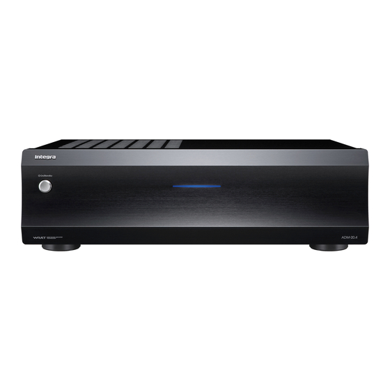
Front Panel For detailed information, see the pages in parentheses. ON/STANDBY button Power indicator This button is used to turn the main power on/off. The power indicator will be lit blue when the main power of ADM-20.4 is turned on. -
Page 6: Rear Panel
These are the analog audio inputs and outputs. Use an ADM-20.4. RCA-type audio connection cable to connect the To turn on the ADM-20.4 with the signal input from output jacks of the device to the INPUT jacks on the the 12V TRIGGER IN jack, set the TRIGGER switch ADM-20.4. -
Page 7: Connections
Wrong! Connecting the AV Receiver When connecting the ADM-20.4 to AV Receiver, connect the INPUT jacks of the ADM-20.4 to the PRE OUT jacks of the AV Receiver, and connect the front speakers to the SPEAKERS terminals of the ADM-20.4. -
Page 8: Connecting Your Speakers
Connecting Your Speakers Note Right Left • Pay close attention to speaker wiring polarity. In other words, connect positive (+) terminals only to positive (+) terminals, and negative (–) terminals only to negative (–) terminals. If you get Speakers them the wrong way around, the sound will be out of phase and will feel unnatural. -
Page 9: Advanced Operations
Switch the TRIGGER selector on the unit’s rear panel. Switch the AUTO STANDBY selector on the unit’s [12V TRIGGER] rear panel. The ADM-20.4 will be turned on when the 12V TRIGGER jacks are provided with power. [ON] Enables auto standby. -
Page 10: Others
• Bad connections or wiring. Turn on the ADM-20.4 and select the input on the Check connections, speaker cables, etc. control amplifier or preamplifier. • The INPUT LEVEL control is set to MIN. -
Page 11: Specifications
Specifications Rated Output Power (FTC) 75 watts minimum continuous power per channel, 8 ohm loads, 2 channels driven at 1 kHz, with a maximum total harmonic distortion of 0.08 % (FTC) 65 watts minimum continuous power per channel, 4 ohm loads, 2 channels driven at 1 kHz, with a maximum total harmonic distortion of 0.08 % THD+N (Total Harmonic Distortion+N) 0.08 % (Rated Output Power) - Page 12 Integra Division of 18 park Way, Upper Saddle River, N.J. 07458, U.S.A. Tel: 201-818-9200 Fax: 201-785-2650 http://www.integrahometheater.com Integra Division of Sales & Product Planning Div.: 2-1, Nisshin-cho, Neyagawa-shi, OSAKA 572-8540, JAPAN Tel: 072-831-8023 Fax: 072-831-8163 C1210-1 SN 29401278 (C) Copyright 2012 Onkyo Corporation Japan. All rights reserved.
Need help?
Do you have a question about the ADM-20.4 and is the answer not in the manual?
Questions and answers