Table of Contents
Advertisement
Quick Links
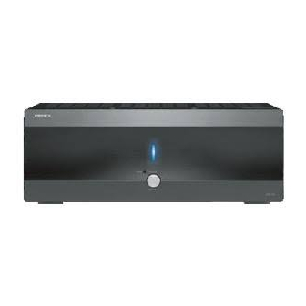
Seven Channel Amplifier
DTA-9.4
Instruction Manual
Thank you for purchasing the Integra Seven
Channel Amplifier.
Please read this manual thoroughly before making
connections and plugging in the unit. Following the
instructions in this manual will enable you to obtain
optimum performance and listening enjoyment from
your new Seven Channel Amplifier. Please retain this
manual for future reference.
Contents
Before using
Operations
Connections
Appendix
E
n
Advertisement
Table of Contents

Related Manuals for Integra DTA-9.4


Summary of Contents for Integra DTA-9.4
- Page 1 Seven Channel Amplifier DTA-9.4 Instruction Manual Thank you for purchasing the Integra Seven Channel Amplifier. Please read this manual thoroughly before making connections and plugging in the unit. Following the instructions in this manual will enable you to obtain optimum performance and listening enjoyment from your new Seven Channel Amplifier.
-
Page 2: Important Safeguards
WARNING: TO REDUCE THE RISK OF FIRE OR ELECTRIC SHOCK, DO NOT EXPOSE THIS APPLIANCE TO RAIN OR MOISTURE. CAUTION: TO REDUCE THE RISK OF ELECTRIC SHOCK, DO NOT REMOVE COVER (OR BACK). NO USER-SERVICEABLE PARTS INSIDE. REFER SERVICING TO QUALIFIED SERVICE PERSONNEL. -
Page 3: Fcc Information For User
2. AC Fuse The fuse is located inside the chassis and is not user-serviceable. If power does not come on, contact your Integra/Onkyo authorized service station. 3. Care From time to time you should wipe the front and rear panels and the cabinet with a soft cloth. -
Page 4: Table Of Contents
Operations Quick operation guide ... 7 Front panel facilities ... 8 Connections Rear panel facilities and connections ... 9 Connecting speakers ... 11 Connecting to the Integra AV Controller DTC-9.4 ... 12 Appendix Troubleshooting guide ... 13 Specifications ... 14... -
Page 5: Supplied Accessories
Supplied accessories Check that the following accessories are supplied with the DTA-9.4. Power cord × 1 Stereo mini-plug cable × 1 (for connecting to the 12V TRIGGER IN terminal on the CONTROL LINK-compatible Integra/Onkyo products) -
Page 6: Precautions
A minimum of four inches is required behind the DTA-9.4 to allow room for the cables and cords without excessively bending them. Do not place the DTA-9.4 near TV or radio. This may cause noise or instable video on radio or TV respectively. Power cord Do not use a power cord other than the one supplied with the DTA- 9.4. -
Page 7: Quick Operation Guide
DTA-9.4 and for a more pleasurable experience with the DTA-9.4. Be sure to read the rest of this manual as well after reading this quick guide. -
Page 8: Front Panel Facilities
(See page 10 for information on the 12V TRIGGER IN terminal.) Note: If you wish to turn on the DTA-9.4 again after it is turned off, wait for 30 seconds or more. Standby indicator and When the Power switch is pressed, either indicator will light like following. -
Page 9: Rear Panel Facilities And Connections
• Read the instructions that came with the other components you are connecting. • Do not make connections to input or output jacks while the DTA-9.4 is turned on (Power • Turn the volume of the control amplifier down before turning on the DTA-9.4. - Page 10 Power outlet on the wall. Power cord (supplied) • Do not plug the DTA-9.4 into the AC outlet other than an AC wall socket. Avoid using the AC OUTLET of the control amplifier as power supply outlet for the DTA-9.4.
-
Page 11: Connecting Speakers
Connect the red (+) output terminal on the DTA-9.4 to the (+) terminal on the speaker, and the white (–) output terminal on the DTA-9.4 to the (–) terminal on the speaker. Use the marking or line on the speaker cord to connect appropriate terminals. Be sure to match the speaker polarity for in-phase connection by connecting (+) terminal to (+) terminal and (–) terminal to (–) terminal between the... -
Page 12: Connecting To The Integra Av Controller Dtc-9.4
Connecting to the Integra AV Controller DTC-9.4 Since many users will purchase the DTA-9.4 together with the DTC-9.4, here is an explanation of how to connect the DTA-9.4 to the DTC-9.4. Balanced input/output connection Note: • When using the balanced inputs, do not connect anything to the RCA inputs. -
Page 13: Troubleshooting Guide
Troubleshooting guide If the DTA-9.4 fails to function normally, first check the following points before contacting your Integra/Onkyo dealer. If the problem is not solved after going through the following list, unplug the power cord and contact your Integra/Onkyo authorized service center. -
Page 14: Specifications
Specifications Amplifier section Continuous average power output (FTC Power, Rated Power) (Measured with AES-17 LPF) Front L/R: 120 Watts per channel min. RMS. Into 8 ohms 2 channel driven, from 20 to 20,000 Hz with no more than 1 % total harmonic distortion. - Page 15 Memo...
- Page 16 Integra Division of ONKYO U.S.A. CORPORATION 18 Park Way, Upper Saddle River, N.J. 07458, U.S.A. Tel: 201-785-2600 Fax: 201-785-2650 http://www. integrahometheater.com Integra Division of ONKYO CORPORATION Sales & Product Planning Div. : 2-1, Nisshin-cho, Neyagawa-shi, OSAKA 572-8540, JAPAN Tel: 072-831-8111 Fax: 072-831-8124...
Need help?
Do you have a question about the DTA-9.4 and is the answer not in the manual?
Questions and answers