Dell 1600n - Multifunction Laser Printer B/W Service Manual
Laser mfp
Hide thumbs
Also See for 1600n - Multifunction Laser Printer B/W:
- User manual (189 pages) ,
- Owner's manual (134 pages) ,
- Specifications (2 pages)

Related Manuals for Dell 1600n - Multifunction Laser Printer B/W


Summary of Contents for Dell 1600n - Multifunction Laser Printer B/W
-
Page 1: Table Of Contents
Easy as Dell Laser MFP 1600n SERVICE Manual Dell Laser MFP CONTENTS 1. Precautions 2. Reference Information 3. Specifications 4. Summary of product 5. Disassembly and Reassembly 6. Alignment and Adjustments 7. Troubleshooting 8. Exploded Views and Parts List 9. Block Diagram 10. - Page 2 © Copyright Dell Inc. May. 2004...
-
Page 3: Precautions
Precautions 1. Precautions In order to prevent accidents and to prevent damage to the equipment please read the precautions listed below carefully before servicing the printer and follow them closely. 1.1 Safety Warning (1) Only to be serviced by appropriately qualified service engineers. High voltages and lasers inside this product are dangerous. -
Page 4: Caution For Safety
Precautions 1.2 Caution for safety 1.2.1 Toxic material This product contains toxic materials that could cause illness if ingested. (1) If the LCD control panel is damaged it is possible for the liquid inside to leak. This liquid is toxic. Contact with the skin should be avoided, wash any splashes from eyes or skin immediately and contact your doctor. -
Page 5: Handling Precautions
Precautions 1.2.3 Handling Precautions The following instructions are for your own personal safety, to avoid injury and so as not to damage the printer (1) Ensure the printer is installed on a level surface, capable of supporting its weight. Failure to do so could cause the printer to tip or fall. -
Page 6: Disregarding This Warning May Cause Bodily Injury
Precautions 1.2.5 Disregarding this warning may cause bodily injury (1) Be careful with the high temperature part. The fuser unit works at a high temperature. Use caution when working on the printer. Wait for the fuser to cool down before disassembly. (2) Do not put finger or hair into the rotating parts. -
Page 7: Esd Precautions
Precautions 1.3 ESD Precautions Certain semiconductor devices can be easily damaged by static electricity. Such components are commonly called “Electrostatically Sensitive (ES) Devices”, or ESDs. Examples of typical ESDs are: integrated circuits, some field effect transistors, and semiconductor “chip” components. The techniques outlined below should be followed to help reduce the incidence of component damage caused by static electricity. -
Page 8: Reference Information
Reference Information 2. Reference Information This chapter contains the tools list, list of abbreviations used in this manual, and a guide to the location space required when installing the printer. A definition of tests pages and Wireless Network information definition is also included. 2.1 Tool for Troubleshooting The following tools are recommended safe and easy troubleshooting as described in this service manual. -
Page 9: Acronyms And Abbreviations
Reference Information 2.2 Acronyms and Abbreviations The table in the below explains abbreviations used in this service manual. The contents of this service manual are declared with abbreviations in many parts. Please refer to the table. Alternating Current Intelligent Drive electronics or Imbedded Drive Electronics Automatic Document Feeder IEEE... -
Page 10: The Sample Pattern For The Test
Reference Information 2.3 The Sample Pattern for the Test The sample pattern shown in below is the standard pattern used in a factory. The contents of the life span and the printing speed are measured with the pattern shown in below. (The picture in the manual is 70% size of the actual A4 size.) 2.3.1 A4 5% Pattern Service Manual... - Page 11 Reference Information 2.3.2 A4 2% Pattern Service Manual...
- Page 12 Reference Information 2.3.3 A4 IDC 5% Patten Service Manual...
-
Page 13: A4 Iso 19752 Standard Pattern
Reference Information 2.3.4 A4 ISO 19752 Standard Pattern This test page is reproduced at 70% of the normal A4 size Service Manual... -
Page 14: Specifications
Specfications are correct at the time of printing. Product specifications are subject to change without notice. See below for product specifications. 3.1 General Specifications Items Tag Heuer Remarks SCX-4920N/DELL Major Features Fax, Copier, Print, Scan, ADF, N/W Print, Scan-to-Email Size (W*D*H) w/o Hand Set 450mmx423mmx456mm) (17.7x16.7x18") - Page 15 Specifications Items Tag Heuer Remarks SCX-4920N/DELL Pickup Roller 150,000 Pages Investigating new material Periodic Replacing to prolong life of pickup Parts rollerSamsung confirm 150,000 Pages reliability. Pad Unit(Tray) 150,000 Pages Samsung confirm 150,000 Pages reliability. Pad Unit (ADF) 20,000 Pages...
-
Page 16: Print Specification
Specifications 3.2 Print Specification Items Tag Heuer Remarks SCX-4920N/DELL PRINT Print Speed 22ppm/Ltr, 20ppm/A4 (600 dpi) Print Emulation GDI, PCL6, PCL5e PostScript Level3(Clone) Auto Emulation Sensing Font Type 45 Scalable, 1 Bitmap Number Power Save Yes(5/10/15/30/45min.) Resolution Normal 600x600dpi (1200x1200,) -
Page 17: Scan Specification
Specifications 3.3 Scan Specification Items Tag Heuer Remarks SCX-4920N/DELL SCAN Scan Method Color CCD Scan Speed Linearity Approx. 75sec (USB 1.1) USB 1.1, 300dpi, Letter Size, through ADF Gray Approx. 75sec (USB 1.1) Pentimum 4 1.xGHz, Color Approx. 150sec (USB 1.1) -
Page 18: Copy Specification
Specifications 3.4 Copy Specification Items Tag Heuer Remarks SCX-4920N/DELL Copy Quality COPY Text 600x300dpi Selection or Text/Photo 600x300dpi Original Image type selection Photo 600x600dpi for Platen Mode Other FCOT Stand by Approx. 10 seconds:Platen Approx. 15 seconds:ADF From Cold Status 50 seconds... - Page 19 Specifications Items Tag Heuer Remarks SCX-4920N/DELL TELEPHONE Handset On hook Dial Search Yes(Phone Book) by using Phone Book Button(Same as Rocky) 1-Touch Dial 10 Numeric Key pad (No dedicated keys) Speed Dial 200 locations(00~199) Total locations can be stored include 1-touch dials...
-
Page 20: Fax Specification
Specifications 3.5 Fax Specification Items Tag Heuer Remarks SCX-4920N/DELL Compatibility ITU-T G3 Communication System PSTN/PABX Modem Speed 33.6Kbps TX Speed 3sec LTRr/MMR Compression MH/MR/MMR/JPEG Color Fax Yes(Send Only) Resolution 203*98dpi Fine 203*196dpi S.Fine 300*300dpi Scan Speed 2.5 sec/ LTR 1,200 PPS (ADF) Fine/S.Fine... - Page 21 Specifications 3.6 Other Specification Items Tag Heuer Remarks SCX-4920N/DELL Network Option Yes (Standard) Protocol SPX/IPX, TCP/IP, Ethertalk, SNMP, HTTP 1.1, DLC/LLC Operating System MS Windows 98/2000/XP/NT/Me, MAC (English only, no status monitor, web download only) Paper Handling Capacity( 20lbs) Main Tray...
- Page 22 Specifications Items Tag Heuer Remarks SCX-4920N/DELL Side 3.5/277mm (1st Tray) 4.0/277mm (2nd Tray) Software Compatibility Win 3.x Win 95 Win 98 Win ME Win NT 4.0 Win 2000 Win XP English only web version Linux WHQL Yes for 2000 & XP...
- Page 23 Specifications MEMO Service Manual 3-10...
-
Page 24: Summary Of Product
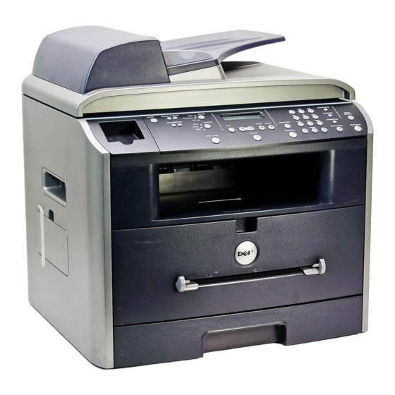
Summary of Product 4. Summary of Product This chapter describes the functions and operating principal of the main component. 4.1 Printer Components 4.1.1 Front View Service Manual... -
Page 25: Rear View
Summary of Product 4.1.2 Rear View Use the: When you want to: Automatic Document Load the document for copying, scanning, or Feeder sending faxes. Operator Panel Operate the machine. Paper O utput Keep print media from falling off the front Extension output tray. - Page 26 Summary of Product Use the: When you want to: Document Cover Open to place a document on the scanner glass. Document Input Tray Load the document for copying, scanning and sending faxes. Document Guides Ensure proper document feeding. Rear Cover Open to remove the paper jams and use the rear output slot when you print the documents from the Bypass tray.
-
Page 27: Control Panel
Summary of Product 4.1.3 Control Panel Service Manual... - Page 28 Summary of Product Service Manual...
-
Page 29: System Layout
Summary of Product 4.2 System Layout 4.2.1 Feeding section There is a universal cassette, which supplies paper to the machine, and the manual feeder, which supplies paper one by one. The cassette has the friction pad, which separates paper one by one and prevent multi- sheet feeding. - Page 30 Summary of Product 4.2.4.5 Safety Relevant Facts • Protecting device when overheating - 1st protecting device: H/W cuts off when detecting an overheating - 2nd protecting device: S/W cuts off when detecting an overheating - 3rd protecting device: Thermostat cuts off the power •...
- Page 31 Summary of Product 4.2.6 LSU (Laser Scanner Unit) The LSU unit is controlled by the video controller. It scans the video data received from video controller with laser beam by using a rotating polygon mirror to create the latent image on the OPC drum. The OPC drum rotates as the same speed as the paper feeding speed.
-
Page 32: Toner Cartridge
Summary of Product 4.2.7 Toner Cartridge By using the xerographic process, it creates a visual image. The Toner Cartridge contains the OPC Drum, developer and toner components in one unit. The OPC unit contains the OPC drum and charging roller. The developer unit contains toner, toner cartridge, supply roller, developing roller, and blade (Doctor blade) - Developing Method: Non magnetic 1 element contacting method - Toner: Non magnetic 1 element shatter type toner... -
Page 33: Main Pba
Summary of Product 4.3 Main PBA It is the functional center of the product. It controls the basic machine operations including the fax, scan, printer operations, sensor detection and power levels. 7 22 7 21 7 24 7 20 7 17 7 19 7 18 7 16... - Page 34 Summary of Product MOTOR DRIVER(TEA3718SFP) U6 MOTOR DRIVER(TEA3718SFP) U12 QUAD 2-INPUT OR GATE(74VHX32) U10 QUAD 2-INPUT OR GATE(74VHX32) U7 QUAD 2-INPUT OR GATE(74VHX32) U70 VEDIC X-TAL(19.6MHz) OSC2 PROCESSOR ASIC(SPGPM) U33 CPU X-TAL(12MHz) OSC10 USB 2.0(NET2272) U48 VARTA(3.6V BATT) RELAY(HRSIKH) RE1 SDRAM(K4S281632E) U43 SDRAM(K4S281632E) U44 MODEM(CXB2500-11) U52...
-
Page 35: Flash Memory
Summary of Product 4.3.1 ASIC Samsung’s S3C46Q0X 16/32-bit RISC micro controller is designed to provide a cost-effective, low power, small die size and high performance micro-controller solution for MFP. The S3C46Q0X is developed using ARM7TDMI core, 0.18(m CMOS standard cell, and memory cell. •... -
Page 36: Sensor Input Circuit
Summary of Product 4.3.4 Sensor input circuit 1) Paper Empty Sensor The Paper empty sensor (Photo Interrupter) on the engine board informs the CPU as to whether the cassette is empty or not with operation of the actuator. When the cassette is empty, it detects the fact by reading the D0 Bit of CPU. It highlights this by selecting the second LED(yellow) among the panel LEDs. - Page 37 Summary of Product 4.4 SMPS & HVPS The SMPS supplies the DC power to the system. It takes 110V/220V and outputs the 5V, 12V and 24V to supply the power to the main board and ADF board. The HVPS part creates the high voltage of THV/MHV/Supply/Dev and supplies it to the developer part for making the best condition to display the image.
- Page 38 Summary of Product 4.4.1 HVPS(High Voltage Power Supply) 1) Transfer High Voltage (THV+) - Function : Voltage to transfer developed toner on OPC drum to a paper. - Output voltage : +1300V DC±20V - Error : If THV (+) doesn't output, a ghost status (same character is printed after one cycle (76mm) of OPC) with a low density occurs due to a toner on OPC drum cannot normally transfer to a paper.
- Page 39 Summary of Product 4.4.2 SMPS(Switching Mode Power Supply) It is the power source of entire system. It is assembled by an independent module, so it is possible to use for common use. It is mounted at the bottom of the set. It is consisted of the SMPS part, which supplies the DC power for driving the system, and the AC heater control part, which supplies the power to fuser.
-
Page 40: Fuser Ac Power Control
Summary of Product 6) Feature - Insulating resistance : over 50M (at DC500V) - Insulating revisiting pressure : Must be no problem within 1min. (at 1500Vzc, 10mA) - Leaking voltage : under 3.5mA - Running voltage : under 40A peak (at 25°c, Cold start) Under 60A peak (in other conditions) - Rising Time : Within 2Sec - Falling Time : Over 20ms - Surge : Ring Wave 6KV-500A (Normal, Common) - Page 41 Summary of Product 4.5 Engine F/W 4.5.1 Feeding If feeding from a cassette, the drive of the pickup roller is controlled by controlling the solenoid. The on/off of the solenoid is controlled by controlling the general output port or the external output port. If feeding from a manual feeder, insert the paper according to the operation of the manual sensor, and by driving the main motor, insert the paper in front of the feed sensor.
- Page 42 Summary of Product 4.5.4 Fusing The temperature change of the heat roller’s surface is changed to the resistance value through the thermis- tor. By converting the voltage value to a digital value, through the AD converter, the temperature is decided. The AC power is controlled by comparing the target temperature to the value from the thermistor.
-
Page 43: Liu Pba
Summary of Product 4.6 LIU PBA LIU board is a Line interface unit, and it is a circuit for interfacing a telephone line with a modem. The circuit is consist- ed of matching transfer to conform to impedance of a receiving telephone line and a circuit to conform to impedance of a modem. -
Page 44: Disassembly And Reassembly
Precautions 5. Disassembly and Reassembly 5.1 General Precautions on Disassembly When you disassemble and reassemble compo- Releasing Plastic Latches nents, you must use extreme caution. The close proximity of cables to moving parts makes proper Many of the parts are held in place with plastic routing a must. -
Page 45: Rear Cover
Precautions 5.2 Rear Cover 1. Remove the four screws securing the Rear Cover. 3. Unlatch the (Cover Face Up) securing the Rear cover, as shown below.Then lift the (Cover Face Up) out. Cover Face Up 2. Remove the Rear Cover from the Frame Ass'y and Scanner Ass'y. - Page 46 Precautions 5.3 Side Cover (LH, RH) 1. Before you remove the Side Cover (LH, RH), you 4. Open the front cover and remove the 2 screws on the should remove: front side. Push the side cover(LH) to the left and - Rear Cover (see page 5-2) remove it from the Frame Assembly.
-
Page 47: Front Cover
Precautions 5.4 Front Cover 1. Open the Front Cover. 2. Unlatch the Front Cover securing the Frame Ass'y. Then remove the Front Cover, as shown below. Front Cover Service Manual... - Page 48 Precautions 5.5 Scanner Ass'y 1. Before you remove the Scanner Ass'y, you should 4. Pull up the Scanner Ass'y, as shown below. remove: - Rear Cover (see page 5-2) - Side Cover (LH, RH) (see page 5-3) 2. Remove the 2 screws securing the Scanner Ass'y, as shown below.
- Page 49 Precautions 6. Remove the Scaner Harness Cable. 8. Remove the 3 screws and the connector and remove the OPE unit as shown below. 9. Remove the 4 screws securing the Scan Upper. 7. Lift the front part of the cover OPE dummy to release the hook connecting the cover with the scan assem- bly.
- Page 50 Precautions 11. Remove the CCD Cable, as shown below. 13. Push the Belt Holder and take out the Belt, as shown below. Spring Belt CCD Cable 12. Pull up the CCD Shaft and take out the Scanner Module. 14. Remove the Reduction Gear and Idle Gear, as shown below.
- Page 51 Precautions 15. Remove the 3 screws and take out the Motor 17. Unlatch the Open Sensor and remove it, as shown Bracket. below. Motor Braket Open Sensor 16. Unplug the one connector from the Open Sensor 18. Remove the Holder CCD Ass'y.
- Page 52 Precautions 5.6 ADF Motor Ass'y 1. Before you remove the ADF Motor Ass'y, you should 5. Remove the 2 screws securing the Upper Cover and remove: remove it, as shown below. - Rear Cover (see page 5-2) - Side Cover (LH, RH) (see page 5-3) - Scanner Ass’y (see page 5-5) Upper Cover 2.
-
Page 53: Ope Unit
Precautions 5.7 OPE Unit 1. Before you remove the OPE Unit, you should remove: 4. Remove the Key Pad from the OPE Cover. - Rear Cover (see page 5-2) - Side Cover (LH, RH) (see page 5-3) - Scanner Ass’y (see page 5-5) 2. -
Page 54: Rear Cover (See Page
Precautions 5.8 Middle Cover & Exit Roller 1. Before you remove the Exit Roller, you should .4. Remove the Exit Gear and Bearing, as shown below. remove: - Rear Cover (see page 5-2) Bearing - Side Cover (LH, RH) (see page 5-3) - Scanner Ass’y (see page 5-5) Exit Roller Exit Gear... -
Page 55: Side Cover (Lh, Rh) (See Page
Precautions 5.9 Controller Shield Ass’y 1. Before you remove the Main PBA, you should remove: 4. Remove the 2 screws connecting the LIU to the - Rear Cover (see page 5-2) Controller Shield Ass'y and remove the LIU. - Side Cover(LH, RH) (see page 5-3) 2. - Page 56 Precautions 5.10 Engine Shield Ass’y & Exit Board 1. Before you remove the Engine Shield Ass'y, you 3. Remove the 12 screws securing the Engine Shield should remove: Ass'y and remove it. Then unplug the all the connec- - Rear Cover (see page 5-2) tors from the Main PBA and SMPS.
-
Page 57: Scanner Ass'y (See Page
Precautions 5.11 SMPS 1. Before you remove the SMPS, you should remove: 4. Remove the 4 screws securing the SMPS. Then lift - Rear Cover (see page 5-2) the SMPS out, as shown below. - Side Cover(LH, RH) (see page 5-3) - Scanner Ass’y (see page 5-5) SMPS - Engine Shield Ass’y(see page 5-12) - Page 58 Precautions 5.12 Fuser Ass'y 1. Before you remove the Fuser Ass'y, you should 4. Remove the 2 screws securing the Halogen Lamp. remove: Then take out the Halogen Lamp from the Heat Roller - Rear Cover (see page 5-2) 2. Unplug the two connectors from the Main PBA and Heat Roller SMPS, as shown below.
- Page 59 Precautions 6. Unwrap the Thermistor Harness, as shown below. 7. Remove the one screw securing the Thermister and remove it, as shown below. Thermistor Thermistor Service Manual 5-16...
- Page 60 Precautions 5.13 Fan 1. Before you remove the Fan, you should remove: 2. Unplug the connector from the SMPS and remove the - Rear Cover (see page 5-2) one screw. Then take out the Fan. - Side Cover (RH) (see page 5-3) DC Fan Service Manual 5-17...
- Page 61 Precautions 5.14 LSU 1. Before you remove the LSU, you should remove: 3. Unplug the two connectors. - Rear Cover (see page 5-2) - Side Cover (LH, RH) (see page 5-3) - Scanner Ass’y (see page 5-5) - Front Cover (see page 5-4) - Middle Cover (see page 5-11) 2.
- Page 62 Precautions 5.16 Drive Ass'y 1. Before you remove the Drive Ass'y, you should 3. Take out the Drive Ass'y, then unplug the connector remove: from the Motor PBA, as shown below. - Rear Cover (see page 5-2) - Side Cover (LH) (see page 5-3) - Shield Controller Ass’y (see page 5-9) 2.
-
Page 63: Front Cover (See Page
Precautions 5.17 Transfer Ass'y 1. Before you remove the Transfer Ass'y, you should 4. Remove the transfer roller by pressing the hook remove: securing the roller to the right using a tool. - Rear Cover (see page 5-2) - Side Cover (LH, RH) (see page 5-3) - Scanner Ass’y (see page 5-5) - Front Cover (see page 5-4) - Middle Cover (see page 5-11) - Page 64 Precautions 5.18 Feed Ass'y 1. Before you remove the Feed Ass'y, you should 4. Remove the 3 screws securing the Feed Bracket and remove: remove it. - Rear Cover (see page 5-2) - Side Cover (LH, RH) (see page 5-3) - Scanner Ass’y (see page 5-5) Feed Bracket - Front Cover (see page 5-4)
- Page 65 Precautions 6. Remove the Feed Gear1 Ass'y. 7. Pull up the Feed Roller and Feed Roller1. Feed Roller Feed Gear1 Ass’y Feed Roller1 Service Manual 5-22...
- Page 66 Precautions 5.19 Pick-Up Ass'y & Solenoid 1. Before you remove the Pick-Up Ass'y, you should 4. Remove the 2 s securing the Manual Solenoid and remove: Pick-Up Solenoid. Then remove Manual Solenoid and - Rear Cover (see page 5-2) Pick-Up Solenoid. - Side Cover (LH, RH) (see page 5-3) - Front Cover (see page 5-4) - Scanner Ass’y (see page 5-5)
-
Page 67: Alignment And Adjustments
6. Alignment and Adjustments This chapter describes the main functions for service, such as the product maintenance method, the test output related to maintenance and repair, DCU using method, Jam removing method, and so on. It includes the contents of manual. 6.1 Paper path Scanner Part Doc-Paper(30Sheets) -
Page 68: Printer Paper Path
6.1.1 Copy & Scan Document Path Scanner Part White-Sheet White-Sheet CCD-Module 6.1.2 Printer Paper Path 1) After receiving print job, the printer feeds the printing paper from the cassette or manual feeder. 2) The fed paper passes the paper feeding sensor. (Jam 0 occurs if the sensor is not operated after certain time passes) 3) The paper passed the paper feeding sensor moves to the paper exit sensor via printing process. -
Page 69: Clearing Paper Jams
6.2 Clearing Paper Jams Occasionally, paper can be jammed during a print job. Some of the causes include: • The tray is loaded improperly or overfilled. • The tray has been pulled out during a print job. • The front cover has been opened during a print job. •... -
Page 70: Clearing Document Jams
6.2.1 Clearing Document Jams If a document jams while it is feeding through the ADF (Automatic Document Feeder),“DOCUMENT JAM ” appears on the display. 6.2.1.1 Input Misfeed 1) Open the ADF top cover. ADF. 3) Close the ADF top cover.Then load the documents back into the ADF. - Page 71 6.2.1.2 Exit Misfeed 1) Open the document cover and turn the release knob to remove the misfed documents from the exit area. 2) Close the document cover.Then load the documents back into the ADF. 6.2.1.3 RollerMisfeed 1) Open the document cover. 2) Turn the release knob so that you can easily remove the misfed document,and remove the document from the ADF or the feed area by carefully pulling it...
- Page 72 6.2.2 Clearing Paper Jams If paper jams occur,“PAPER JAM ” appears on the display..Refer to the table below to locate and clear the paper jam. PAPER JAM 0 : In the paper feed area PAPER JAM 2 : In the paper exit area PAPER JAM 1 : In the fuser area or around the toner cartridge BYPASS JAM...
- Page 73 6.2.2.2 JAM 2 (In the Paper Exit Area) 4) Remove the jammed paper by gently pulling it 1) Open and close the front cover.The jammed paper straight out.. automatically exits the machine. If the paper does not exit,continue to Step 2. 2) Gently pull the paper out of the front output tray.
- Page 74 6.2.2.3 JAM1 (In the Fuser Area of Around the Toner Cartridge Area) NOTE : The fuser area is hot.Be careful when removing paper from the machine. 1) Open the front cover and remove the toner cartridge. 3) Replace the toner cartridge and close the front cover. Printing automatically resumes.
-
Page 75: Tips For Avoiding Paper Jams
6.2.2.4 BYPASS JAM (In the Bypass Tray) “BYPASS JAM ” appears on the display when the machine does not detect paper in the Bypass tray due to no paper or improper paper loading when you try to print using the Bypass tray. “BYPASS JAM ”... -
Page 76: Paper Setting
6.3 User Mode(SCX-4920N) The table in the bellow explains the possible setting functions by user. The details about the ways to use are explained in the user manual. In the service manual, the items are about the possible set-up by user. 6.Reports 1.Paper Setting 2.Copy Setup... - Page 77 6.3 User Mode(SCX-4920N) The table in the bellow explains the possible setting functions by user. The details about the ways to use are explained in the user manual. In the service manual, the items are about the possible set-up by user. 1.Paper Setting 2.Copy Setup 3.Fax Setup...
-
Page 78: Tech Mode
6.4 Tech Mode 6.4.1 How to Enter Tech Mode In service (tech) mode, the technician can check the machine and perform various test to isolate the cause of a malfunction. While in Tech mode, the machine still performs all normal operations. To enter the Tech mode To enter the Tech mode, press in sequence, and the LCD... -
Page 79: Data Setup
6.4.3 Data Setup SEND LEVEL You can set the level of the transmission signal. Typically, the Tx level should be under -12 dBm. Caution : The Send Fax Level is set at the best condition in the shipment from factory. Never change settings arbitrarily. -
Page 80: Flash Upgrade
FLASH UPGRADE The Firmware Upgrade function and has two methods, Local and Remote. (1) Local Machine • RCP(Remote Control Panel) mode This method is for Parallel Port.or USB Port Connect to PC and activate RCP(Remote Control Panel) to upgrade the Firmware. <... -
Page 81: Switch Test
6.4.4 Machine Test SWITCH TEST Use this feature to test all keys on the operation control panel. The result is displayed on the LCD window each time you press a key. MODEM TEST Use this feature to hear various transmission signals to the telephone line from the modem and to check the modem. -
Page 82: Protocol List
6.4.5 Report PROTOCOL LIST This list shows the sequence of the CCITT group 3 T.30 protocol during the most recent sending or receiving operation. Use this list to check for send and receive errors. If a communication error occurs while the machine is in TECH mode, the protocol list will print automatically. -
Page 83: Engine Test Mode
6.5 Engine Test Mode The Engine Tests Mode supplies useful functions to check the condition of the engine. It tests the condition of each device and displays the result of the test on the LCD. It is classified into 5 functions (0~4), and are shown below. Outline - In order to enter “Engine Test ”... - Page 84 6.5.3 Detail Description(Engine Test Mode) Function Name Description Display 01.Motor Test The main motor keeps running after the execution key is Main Motor On(Off) chosen and stops when the stop key is chosen. 02.Pick Up Test automatically Tray 1,2 Solenoid On/Off stops, when the execution is chosen.
-
Page 85: Identify Sale Date
6.6 Identify Sale Date This function confirms the date that consumer bought product and used the product for the first time. When the consumer first operate the machine, it will start a scan and page count. The time the machine was first used is remembered. These settings are are remembered after memory delete (Clear All Memory). -
Page 86: Consumables And Replacement Parts
6.7 Consumables and Replacement Parts The cycle period outlined below is a general guideline for maintenance. The example list is for an average usage of 50 transmitted and received documents per day. Environmental conditions and actual use will may vary. The cycle period given below is for reference only. -
Page 87: Abnormal Image Printing And Defective Roller
6.8 Abnormal Image Printing and Defective Roller If abnormal image prints periodically, check the parts shown below. L S U Fuser Toner Cartridge Roller Abnormal image period Kind of abnormal image OPC Drum 75.5mm White spot, Block spot Charge Roller 37.7mm Black spot Supply Roller... -
Page 88: Error Messages
6.9 Error Messages The display on the front panel shows the messages to indicate the printer’s status or errors. Refer to the tables below to understand the message’s meaning and clear the problem if necessary. The messages and their meanings are listed in alphabetical order, with numbered messages following. - Page 89 Group Not Available Meaning: You have tried to select a group location number where only a single location number can be used, such as when adding locations for a broadcasting operation. Solution: Use a speed dial number or dial the number manually using the number keypad. [Hsync Error] [ LSU Error] Meaning: A problem has occurred in the Laser Scanning Unit (LSU).
- Page 90 [Paper Jam 2] Check Outside Meaning: Paper has jammed in the fuser area. Solution: Clear the jam. Power Failure Meaning: The power has been turned off and then on and the printer’s memory has not been saved. Solution: The printer’s memory was not saved due to a power failure. The job will need to be started over. Registered Meaning: The group dial location is already registered with another speed dial number.
-
Page 91: Troubleshooting
Troubleshooting 7. Troubleshooting 7.1 Paper Feeding Problems 7.1.1 Wrong Print Position • Description Printing begins when the paper is in the wrong position. Check and Cause Solution A defective feed sensor actuator can cause incorrect tim- Replace the defective actuator ing. - Page 92 Troubleshooting 7.1.3 JAM 1 1. Recording paper is jammed in front of or inside the fuser. • Description 2. Recording paper is stuck in the discharge roller and in the fuser just after passing through the Actuator-Feed. Check and Cause Solution L S U 1.
-
Page 93: Paper Rolled In The Fuser
Troubleshooting 7.1.5 Multi-Feeding • Description Multiple sheets of paper are fed at once. Check and Cause Solution 1. Solenoid malfunction(the solenoid does not work 1. Replace the solenoid if necessary. properly): Perform Engine Test Mode : Diagnostic Mode code 0. 2. -
Page 94: Defective Adf
Troubleshooting 7.1.7 Paper rolled in the OPC • Description Paper is rolled up in the OPC. Check and Cause Solution 1. Paper is too thin. 1. Recommend to use normal paper thickness. 2. The face of paper is curled. 2. How to remove the rolled paper in the OPC. •... - Page 95 Troubleshooting 7.2. Printing Problems (malfunction) 7.2.1 Defective Operation (LCD WINDOW ) Display • Description Strange characters are displayed on the OPE Panel and buttons are not operated. Check and Cause Solution 1. Clear the memory.(see page 6.5.3) 1. Try again after clearing the memory. 2.
-
Page 96: Paper Empty
Troubleshooting 7.2.3 Not functioning of the fuser gear due to melting away • Description The Motor breaks away from its place due to gear melting away. Check and Cause Solution 1. Check the Heat Lamp. 1. Replace the Fuser. 2. Replace the Main PBA. 3. -
Page 97: Door Open
Troubleshooting 7.2.6 Door Open • Description The ERROR lamp is on even when the print Door is closed. Check and Cause Solution 1. The hook lever in the Front Cover may be defective. 1. Replace the hook lever, if defective. 2. -
Page 98: Defective Motor Operation
Troubleshooting 7.2.8 Defective Motor operation • Description Main Motor is not driving when printing, and paper does not feed into the printer, resulting 'Jam 0'. Check and Cause Solution 1. Motor harness or sub PCB may be defective. 1. Check the Motor harness, replace it, if defective. 2. - Page 99 Troubleshooting 7.2.10 Vertical Line Getting Curved • Description When printing, vertical line gets curved. Check and Cause Solution 1. If the supply of +24v is unstable in the Main Control board 1. Replace LSU. linking with LSU, check drive by Engine Test Mode : Diagnostic Code 1 LSU Motor on.
-
Page 100: Printing Quality Problems
Troubleshooting 7.3 Printing Quality Problems 7.3.1 Vertical Black Line and Band 1. Straight thin black vertical line occurs in the printing. • Description 2. Dark black vertical band occur in the printing. Check and Cause Solution Digital Printer 1. Damaged develop roller in the Developer. 1. -
Page 101: Horizontal Black Band
Troubleshooting 7.3.3 Horizontal Black Band 1. Dark or blurry horizontal stripes occur in the printing periodically. • Description (They may not occur periodically.) Check and Cause Solution Digital Printer 1. Bad contacts of the voltage terminals to 1. Clean each voltage terminal of the Charge, Digital Printer developer. -
Page 102: Light Image
Troubleshooting 7.3.5 Light Image • Description The printed image is light, with no ghost. Check and Cause Solution Digital Printer 1. Develop roller is stained when the toner 1. Check if the Toner Save Mode is off. Digital Printer of developer cartridge is almost con- Digital Printer sumed. -
Page 103: Uneven Density
Troubleshooting 7.3.7 Uneven Density • Description Print density is uneven between left and right. Check and Cause Solution 1. The pressure force on the left and right 1. Replace both the left and right Spring springs of the transfer roller is not even, Holder. - Page 104 Troubleshooting 7.3.9 Ghost (1) • Description Ghost occurs at 75.5 mm intervals of the OPC drum in the whole printing. Check and Cause Solution Digital Printer 1. Bad contacts caused by contamination 1. Clean the contaminated terminals. Digital Printer from toner particles between high voltage Digital Printer terminal in the main body and the elec- Digital Printer...
-
Page 105: Stains On The Front Of The Page
Troubleshooting 7.3.11 Ghost (3) • Description White ghost occurs in the black image printing at 35 mm intervals. Check and Cause Solution Digital Printer Digital Printer 1. The life of the developer may be expired. 1. Problem in the toner cartridge, replace the toner cartridge and try to print out. -
Page 106: Stains On Back Of The Page
Troubleshooting 7.3.14 Stains on back of the page • Description The back of the page is stained at 56.1 mm intervals. Check and Cause Solution Digital 1. Transfer roller is contaminated. 1. Perform the OPC Cleaning Mode Print 2 or Digital Pri 3 times. -
Page 107: No Dial Tone
Troubleshooting 7.4 Fax & Phone Problems 7.4.1 No Dial Tone • Description While on-hook button is pressed, there is no dial tone. Check and Cause Solution 1. Check if the telephone line cord is connected to 1. If the telephone cord is normal but there is no dial tone, TEL LINE correctly. -
Page 108: Defective Fax Forward
Troubleshooting 7.4.3 Defective FAX FORWARD/RECEIVE • Description The FAX FORWARD/RECEIVE is not functioning. Check and Cause Solution 1. Check if you can catch a dial tone by pressing 1. If the MODEM testing is normal and there is no dial OHD. - Page 109 Troubleshooting 7.4.5 Defective FAX RECEIVE (1) • Description FORWARD is functioning, but RECEIVE is not functioning or the received data are broken. Check and Cause Solution 1.Check if there is NOISE when pressing on-hook 1.If it makes NOISE while on-hooking, replace or repair dial.
-
Page 110: Defective Automatic Receiving
Troubleshooting 7.4.8 Defective FAX RECEIVE (4) • Description The received data is reduced by more than 50% in the printing. Check and Cause Solution Check the FAX status of the forwarding side. After checking the data of the forwarding side, correct the FAX of the forwarding side. -
Page 111: Copy Problems
Troubleshooting 7.5 Copy Problems 7.5.1 White Copy • Description Blank page is printed out when copy. Check and Cause Solution 1. Check the Scan-Cover open. 1. Room light ca transit a thin original. 2. Check shading profile. 2. Remake shading profile in the tech mode. 3. -
Page 112: Defective Image Quality
Troubleshooting 7.5.3 Abnormal noise • Description There is noise when copy. Check and Cause Solution 1. Check the Scanner Motor and any mechanical 1. Check the right position of the Scanner Motor, and disturbance. check the any mechanical disturbance in the CCD carriage part. -
Page 113: Scanning Problems
Troubleshooting 7.6 Scanning Problems 7.6.1 Defective PC Scan • Description The PC Scan is not functioning at all. Check and Cause Solution 1. Check the Cable (USB or Parallel) 1. If the PC and the cable are not connected properly, reconnect it. -
Page 114: Service For The Life Of Toner Cartridge
Troubleshooting 7.7 Toner Cartridge Service It is not guaranteed for the default caused by using other toner cartridge other than the cartridge supplied by the Samsung Electronic or caused by non-licensed refill production. 7.7.1 Precautions on Safe-keeping of Toner Cartridge Excessive exposure to direct light more than a few minutes may cause damage to the cartridge. -
Page 115: Signs And Measures At Poor Toner Cartridge
Troubleshooting 7.7.4 Signs and Measures at Poor toner cartridge Fault Signs Cause & Check Solution Light image and • The printed image 1. If the image is light or unclean 1. All of 1, 2, 3 above- partially blank is light or unclean and untidy printed image - (1)The weight of the developer image... - Page 116 Troubleshooting Fault Signs Cause & Check Solution 1. If light or dark periodical black White Black spot • Light or dark black 1. In case of 1 above - dots occur, this is because the dots on the image Run OPC Cleaning Mode Print developer rollers are contami- occur periodically.
- Page 117 Troubleshooting Fault Signs Cause & Check Solution Ghost & Image • The printed image 1. The printed image is too light 1. All of 1, 2, 3 above Contamination is too light or dark, or dark, or partially contami- (1)Remove toner and foreign sub- or partially contami- nated black.
-
Page 118: General Problems
Troubleshooting 7.8 Network Problems Troubleshooting 7.8.1 General Problems Problem Solution System does not function with some wrong Possibly the parameters in PortThru are corrupted.Restart the system values entered y mistake while configuring. and set to factory defaults on the printer front panel or on your computer using SyncThru. -
Page 119: Windows Problems
Troubleshooting 7.8.2 Macintosh Problems Problem Solution The printer name is not displayed in the 1.Make sure the printer is connected to network correctly. Chooser. 2.Make sure the printer is configured in SyncThru using the new name. 3.After turning on the printer,wait 3 minutes,then check it again. 4.Make sure that your Macintosh is connected to the network through Ethernet. -
Page 120: Syncthru Installation Problems
Troubleshooting Problem Solution SyncThru is unable to automatically detect 1.Check LAN cable is connected to the printers. printers. •Check LAN cable is connected to the printers yourself. •Make sure that there are the connected printers shown in network neighborhood.If not, check the communication status of the printers. •If IP address is assigned to the computers, try ping command. -
Page 121: Exploded Views And Parts List
Exploded View & Parts List Up-date On March. 04. 2004 8. Exploded Views and Parts List 8.1 Main Assembly Exploded view ................page(8-2) 8.2 Rx Drive Ass’y Exploded view ................page(8-5) 8.3 ADF Assembly Exploded view ................page(8-6) 8.4 OPE Assembly Exploded view ................. page(8-10) 8.5 Scanner Assembly Exploded view ................. -
Page 122: Main Assembly
Exploded View & Parts List 8.1 Main Assembly Service Manual... - Page 123 JC96-03080A ELA HOU-ADF JC96-03604A COVER-OPE DUMMY R2 JC63-00377A COVER-OPE POCKET JC63-00378A ELA HOU-OPE JC96-03070A ELA HOU-PLATEN JC96-03067A ELA UNIT-FRAME DELL JC96-03098A ELA UNIT-RX DRIVE JC96-03078A UNIT-HUMMINGBIRD LSU JC59-00018B CBF HARNESS-LSU JC39-00321A ELA HOU-SHIELD ASS’Y LV, 110V JC96-03107A 110V ELA HOU-SHIELD ASS’Y HV, 220V...
- Page 124 COVER-REAR R2 JC63-00392A 14-2 COVER-FACE UP R2 JC63-00393A 14-3 MAGNETIC CATCH JC61-00961A 14-4 COUNTER PART JC61-00962A 14-5 LABEL-PORT(REAR-COVER)/330 JC68-01345A BADGE-DELL JC64-00131A CBF HARNESS-MOTOR JC39-00241A MEA ETC TR JC97-01917A 17-1 ROLLER-TRANSFER R2 JC66-00703A 17-2 GEAR-TRANSFER JC66-00395A COVER-MIDDLE FRONT L JC63-00386A COVER-MIDDLE FRONT R...
- Page 125 Exploded View & Parts List 8.2 RX Drive Assembly RX Drive Assembly Parts List SA : Service Available O : Service available X : Service not available Description SEC.Code Q’ty Remark ELA UNIT-RX DRIVE JC96-03078A BRACKET-GEAR MAIN JC61-00891A GEAR-RDCN 53/26 JC66-00388A GEAR-RDCN 113/33 JC66-00706A...
-
Page 126: Adf Assembly
Exploded View & Parts List 8.3 ADF Assembly ADF ASS’Y 1-2-4 1-2-1 1-2-2 1-2-3 3-14 2-16 3-18 3-11 3-18 3-16 3-15 3-17 3-10 3-16 3-20 3-13 3-18 3-19 2-15 3-13 3-12 3-19 2-15 2-17 2-19 2-18 2-12 2-10 2-11 2-19 2-13 2-11 Service Manual... - Page 127 Exploded View & Parts List ADF Assembly Continued. 4-3-2 4-3-4 4-3-3 4-3-1 Service Manual...
- Page 128 Exploded View & Parts List ADF Assembly Parts List SA : Service Available O : Service available X : Service not available Description SEC.Code Q’ty Remark ELA HOU-ADF-ENGINE JC96-03133A MEA UNIT-ADF UPPER JC97-01939A COVER-ADF UPPER R2 JC63-00450A MEA UNIT-HOLDER ADF JC97-01940A 1-2-1 RMO-ADF RUBBER...
- Page 129 Exploded View & Parts List ADF Assembly Parts List(cont.) SA : Service Available O : Service available X : Service not available Description SEC.Code Q’ty Remark GEAR-SWING 31/20 ADF JC66-00457A 3-10 LINK-M-SWING ADF JC66-00454A 3-11 GEAR-58/25 ADF JC66-00455A 3-12 IMPELLER-ADF JC66-00556A 3-13 GEAR-REMOVE ADF...
- Page 130 Exploded View & Parts List 8.4 OPE Unit Assembly Service Manual 8-10...
- Page 131 Exploded View & Parts List OPE Unit Assembly Parts List SA : Service Available O : Service available X : Service not available Description SEC.Code Q’ty Remark ELA HOU-OPE JC96-03070A COVER-OPE R2_DELL JC63-00376A WINDOW-LCD JC64-00130A KEY-COPY_DELL JC64-00120A KEY-START COPY JC64-00126A KEY-CANCEL JC64-00127A KEY-SEND FAX...
-
Page 132: Scanner Assembly
Exploded View & Parts List 8.5 Scanner Assembly 1-3-1 1-3-2 1-3-4 1-3-3 2-15 2-15-4 2-15-3 2-15-7 2-15-6 2-15-5 2-13 2-15-8 2-10 2-11 2-15-1 2-13 2-12 2-15-2 2-16 2-14 Service Manual 8-12... - Page 133 SA : Service Available O : Service available X : Service not available Description SEC.Code Q’ty Remark ELA HOU-PLATEN JC96-03067A MEA UNIT-SCAN UPPER JC97-01942A COVER-SCAN UPPER DELL JC63-00380A GLASS-SCAN JC01-00001A MEA UNIT-SCAN DUMMY JC97-01941A 1-3-1 COVER-SCAN DUMMY R2 JC63-00456A COVER-SCAN DUMMY R2...
-
Page 134: Middle Cover Assembly
Exploded View & Parts List 8.6 Middle Cover Assembly Middle Cover Assembly Parts List SA : Service Available O : Service available X : Service not available Description SEC.Code Q’ty Remark MEA UNIT-COVER MIDDLE JC97-01932A COVER-MIDDLE R2 JC63-00385A COVER-REAR UPPER JC63-00388A COVER-STACKEP RX JC63-00513A... - Page 135 Exploded View & Parts List 8.7 Frame Assembly Service Manual 8-15...
- Page 136 Exploded View & Parts List Frame Assembly Parts List SA : Service Available O : Service available X : Service not available Description SEC.Code Q’ty Remark ELA UNIT-FRAME DELL JC96-03098A FRAME-BASE R2 JC61-00906A GUIDE-P-TR JC61-00607A PLATE-P-SAW JC61-00604A GUIDE-M-TR RIB JC61-00594A...
- Page 137 Exploded View & Parts List Frame Assembly Parts List(Cont.) SA : Service Available O : Service available X : Service not available Description SEC.Code Q’ty Remark IPR-P-EARTH TRANSFER JC70-00307A HOLDER-PTL R2 JC61-00907A LENS-PTL JC67-00027A PMO-BUSHING_TR(L) JC72-00102A SPRING ETC-TR L HAWK JC61-00047A ROLLER-FEED JC66-00598A...
- Page 138 Exploded View & Parts List Frame Assembly Parts List(Cont.) SA : Service Available O : Service available X : Service not available Description SEC.Code Q’ty Remark GROUND-TERMINAL DEVE JC63-00458A PBA SUB-PTL JC92-01620A MEA UNIT-GUIDE PAPER JC97-01924A 57-1 GUIDE-PAPER FRONT JC61-00905A 57-2 SHEET-GUIDE PAPER JC63-00470A...
- Page 139 Exploded View & Parts List 8.8 Fuser Assembly Service Manual 8-19...
- Page 140 Exploded View & Parts List Fuser Assembly Parts List SA : Service Available O : Service available X : Service not available Description SEC.Code Q’ty Remark ELA HOU-FUSER 110V JC96-03061A 110V ELA HOU-FUSER 220V JC96-03062A 220V COVER-FUSER R2 JC63-00363A HOLDER-PLATE CLAW R2 JC61-00886A SPRING ETC-CLAW JC61-00064A...
- Page 141 Exploded View & Parts List 8.9 Cassette Assembly Service Manual 8-21...
- Page 142 Exploded View & Parts List Cassette Assembly Parts List SA : Service Available O : Service available X : Service not available Description SEC.Code Q’ty Remark MEA UNIT-CASSETTE, USA JC97-01919A FRAME-M-CASSETTE JC61-00876A GUIDE-M-EXTENSION LARGE JC61-00918A GUIDE-EXTENSION SMALL JC61-00960A PLATE-P-KNOCK_UP JC61-00603A SPRING-CS 6107-001166 MEA UNIT-HOLDER PAD...
- Page 143 Exploded View & Parts List 8.10 SCF(Option Cassette Frame) Exploded view Service Manual 8-23...
- Page 144 Exploded View & Parts List SCF(Option Cassette Frame) Assembly Parts List SA : Service Available O : Service available X : Service not available Description SEC.Code Q’ty Remark ELAHOU-SCF R2 JC96-03096A COVER-M-FRONT SCF R2 JC63-00364A COVER-M-LEFT SCF R2 JC63-00365A COVER-M-RIGHT SCF R2 JC63-00366A COVER-M-REAR SCF R2 JC63-00367A...
- Page 145 Exploded View & Parts List SCF(Option Cassette Frame) Assembly Parts List SA : Service Available O : Service available X : Service not available Description SEC.Code Q’ty Remark SCREW-TAPTITE 6003-000196 ELA HOU-MOTOR SCF JC96-03003A 39-1 BRKT-P-MOTOR SCF JC61-00879A 39-2 BRKT-P-GEAR SCF JC61-00881A 39-3 BRKT-M-FEED SCF...
- Page 146 Exploded View & Parts List MEMO Service Manual 8-26...
-
Page 147: Block Diagram
Block Diagram 9. Block Diagram Service Manual... -
Page 148: Connection Diagram
Connection Diagram 10. Connection Diagram Service Manual 10-1... -
Page 149: Circuit Description
MAIN MOTOR ROM Control COVER S/W PCL6(2MB x 2ea) MAIN MO TOR DRIVER AC PWR DMA Control A3977SLR PS3(2MB x 2ea) : DELL PS3 / PCL6 DIMM(SEC) GEU/HCT/gCOD ADF UNIT FUSER P-REGI, P-DET, P-POS MEMORY DIMM I/O I/F SENSOR ADF MOTOR DRIVER... -
Page 150: Circuit Diagram
Circuit Diagram Laser MFP 1600n CONNECTION DIAGRAM 1 : P_EMPTY 2 : P_FEED SMPS / HVPS 3,4 : +5V 5,6,8,9,10 : GND 1 : DGND 7 : +12V 11,12 : +24VS OPE B’d 2 : +5V 13 : MP_EMPTY 14 : +24V SENSOR 3 : OPE_TXD 15,22,23 : N.C... - Page 151 Circuit Diagram 2) Flash Memory : Record System Program, and download System Program by PC INTERFACE. FAX for Journal List, and Memory for One Touch Dial, Speed Dial List. - Size : 4M Byte - Access Time : 70 nsec 3) SDRAM : is used as Swath Buffer in Printing, Scan Buffer in Scanning, ECM Buffer in FAX receiving, and System Working Memory Area - size 32MB : 32Mbyte(Basic).
-
Page 152: Fax Section
Circuit Diagram 11.2 FAX Section 11.2.1 Modem Part 11.2.1.1 BLOCK DIAGRAM Transformer CX20493 System Line Side Side Ext Line Dervice Dervice Capacitor Implemented by based on Conexant DAA (Data Access Arrangement) Solution , and is roughly composed of two kinds Chip Solution - CX82500(SFM336) : Existing Modem Chip which adds SSD (System Side Device) for interfacing between - - LSD and DIB of FM336Plus Core - CX20493(LSD) : LIU (Line Interface Unit) Chip which is controlled by SSD and satisfies each PSTN... - Page 153 Circuit Diagram 11.2.1.2 Modem(SFM336) specification • 2-wire half-duplex fax modem modes with send and receive data rates up to 14,400 bps V.17, V.33, V.29, V.27 ter, and V.21 Channel 2 - Short train option in V.17 and V.27 ter • PSTN session starting - V.8 and V.8bis signaling •...
- Page 154 Circuit Diagram 1) Line Interface Signal of Tel Line and LSD is Analog Signal. 2) there is A/D, D/A Converter in LSD, so Analog Signal from Tel Line is transited in Digital through A/D Converter in DAA and transfer to SSD by DIB Capacitor Digital Signal from SSD is converted to Analog by D/A Converter in DAA and transfer to Tel Line CX82500(SFM336) Transformer...
- Page 155 Circuit Diagram 1) Application Network: 3 PSTN (RJ-11) 2) Communication Mode: Half-Duplex, ITU V.8, V.34, V.17, V.29, V.21, ECM > Modem will auto train down only. > . 3) Communication Standard: ITU-T Group 3 4) Max. Modem Speed: 33.6 Kbps 5) Encoding: MH, MR, MMR, JPEG 6) Transfer Rate:...
- Page 156 Circuit Diagram This is Connection Part between system and PSTN(Public Switched Telephone Network), and 1 st side circuit is usually located. Main functions are Line Interface, Telephone Connection and Line Condition Monitoring. 1. Telephone Line Connection • Modular Plug : RJ-11C •...
-
Page 157: Scanner Section
Circuit Diagram 11.3 Scanner Section 11.3.1 Scan Part Pictorial signal input part : output signal of CCD passes through Bypass_Cap change to ADC at AFE_CIP4 , and defined signal between AFE_CIP4 and CIP4 processes the Image signal. When AFE accept each pixel, CDS(Correlated Double Sampling ) technique which samples arm-level twice is used on each pixel by using CIP4 signal. - Page 158 Circuit Diagram 11.3.2 IP Block Diagram CIP4 Oscillation Pad 40MHz Crystal MHIMRIMMR MAIN 20MHz 80MHz CODEC Table2 Line Bufter Table4 Image Enlargement/ Engancement Reduction IRQ Ctrl Motor Control CPU Address Gamma Binarization Vpeak Register Control Control Table1 CPU Data SRAM Data Table3 Shading Extermal...
- Page 159 Circuit Diagram 1) Scanning Device: Color CCD (Charge Coupled Device) Module 2) Supported Operating Systems: Windows 98/2000/NT4.0/ME/XP, MAC (English only, no status monitor, web download only) 3) Compatibility: TWAIN Standard 4) Maximum Scan Width: 216mm (8.5 inches) 5) Effective Scan Width: 208mm (8.2 inches) 6) Optical Resolution: 600x1200 dpi...
-
Page 160: Printer Section
Circuit Diagram 11.4 Printer Section Printer is consisted of the Engine parts and F/W, and said engine parts is consisted of the mechanical parts comprising Frame, Feeding, Developing, Driving, Transferring, Fusing, Cabinet and H/W comprising the main control board, power board, operation panel, PC Interface. The main controller is consisted of Asic(SPGPm) parts, Memory parts, Engine interface parts and it functions as Bus Control, I/O Handing, drivers &... - Page 161 Circuit Diagram 11.4.1 ASIC • ARM946ES - 32-bit RISC embedded processor core - 16KB instruction cache and 16KB data cache - No Tightly Coupled Memory - Memory Protection Unit & CP15 control program • Dual bus architecture for bus traffic distribution - AMBA High performance Bus (AHB) - System Bus with SDRAM •...
- Page 162 Circuit Diagram 11.4.2 Speed : 166MHz core(ARM946ES) operation, 60MHz bus operation ARM946E-S CORE EXTERNAL 16KB ICACHE DMA CONTROLLER USB2.0 16KB DCACHE (4CH) CONTROLLER ADDR/ AHB Bus ARBITER DATA CONTROLLER DECODER SYSTEM SFR BUS INTERFACE INTERFACE SYSMAC CLOCK & RESET GENERATOR SYSTEM PLL (120MHz) HPVC...
-
Page 163: Copier Section
Circuit Diagram 11.5 Copier Section 1) Copy Mode: Black and White 2) Scanner Type: CCD with Flatbed/Platen and ADF 3) Maximum Size of Original: > Platen: 216 x 297 mm > ADF: Legal (216 x 356 mm) (max. width = 218 mm, max length = 400 mm) 4) Optical Resolution: 600 x 600 dpi... - Page 164 Circuit Diagram 11.6 Telephone Section 1) Speed Dial: 200 Locations (46 digits maximum per location) 2) On-hook Dial (manual fax): 3) Last Number Redial: 4) Automatic Redial: 5) Pause: Yes (using Redial key) 6) Ringer Volume: Off, Low, Medium, High 7) Tone/Pulse: Selectable (Tech Mode Only no Telecom certification for Pulse mode) 11.7 SMPS &...
- Page 165 Circuit Diagram • Charge Voltage (MHV) > Input Voltage : 24 V DC & 15% > Output Voltage : -1.3KV ~ -1.8KV DC +/- 50V > Output Voltage Rising Time : 50 ms Max > Output Voltage Falling Time : 50 ms Max >...
- Page 166 Circuit Diagram 11.7.2 SMPS (Switching Mode Power Supply) It is the power source of entire system. It is assembled by an independent module, so it is possible to use for common use. It is mounted at the bottom of the set. It is consisted of the SMPS part, which supplies the DC power for driving the system, and the AC heater control part, which supplies the power to fuser.
- Page 167 Circuit Diagram • Consumption Power ITEM CH2 (+5V) CH3 (+24V) Remark Stand-By 0.07A 0.4 A AVG:55 Wh PRINTING 0.14A 2.0 A AVG 350 Wh Sleep-Mode 0.01A 0.4A AVG : 20 Wh • Length of Power Cord : 1830 & 50mm •...
- Page 168 Circuit Diagram 11.7.3 Fuser Ac Power Control Fuser(HEAT LAMP) gets heat from AC power. The AV power controls the switch with the Triac, a semiconductor switch. The ‘ON/OFF control’ is operated when the gate of the Triac is turned on/off by Phototriac (insulting part). In other words, the AC control part is passive circuit, so it turns the heater on/off with taking signal from engine control part.
-
Page 169: Schematic Diagram
Schematic Diagram 12. Schematic Diagrams 12.1 Dell Schematic Main(1/17) Service Manual 12-1 This Document can not be used without Samsung’s authorization. - Page 170 Dell Schematic Main(2/17) Schematic Diagram Service Manual 12-2 This Document can not be used without Samsung’s authorization.
- Page 171 Dell Schematic Main(3/17) Schematic Diagram Service Manual 12-3 This Document can not be used without Samsung’s authorization.
- Page 172 Dell Schematic Main(4/17) Schematic Diagram Service Manual 12-4 This Document can not be used without Samsung’s authorization.
- Page 173 Dell Schematic Main(5/17) Schematic Diagram Service Manual 12-5 This Document can not be used without Samsung’s authorization.
- Page 174 Dell Schematic Main(6/17) Schematic Diagram Service Manual 12-6 This Document can not be used without Samsung’s authorization.
- Page 175 Dell Schematic Main(7/17) Schematic Diagram Service Manual 12-7 This Document can not be used without Samsung’s authorization.
- Page 176 Dell Schematic Main(8/17) Schematic Diagram Service Manual 12-8 This Document can not be used without Samsung’s authorization.
- Page 177 Dell Schematic Main(9/17) Schematic Diagram Service Manual 12-9 This Document can not be used without Samsung’s authorization.
- Page 178 Dell Schematic Main(10/17) Schematic Diagram Service Manual 12-10 This Document can not be used without Samsung’s authorization.
- Page 179 Dell Schematic Main(11/17) Schematic Diagram Service Manual 12-11 This Document can not be used without Samsung’s authorization.
- Page 180 Dell Schematic Main(12/17) Schematic Diagram Service Manual 12-12 This Document can not be used without Samsung’s authorization.
- Page 181 Dell Schematic Main(13/17) Schematic Diagram Service Manual 12-13 This Document can not be used without Samsung’s authorization.
- Page 182 Dell Schematic Main(14/17) Schematic Diagram Service Manual 12-14 This Document can not be used without Samsung’s authorization.
- Page 183 Dell Schematic Main(15/17) Schematic Diagram Service Manual 12-15 This Document can not be used without Samsung’s authorization.
- Page 184 Dell Schematic Main(16/17) Schematic Diagram Service Manual 12-16 This Document can not be used without Samsung’s authorization.
- Page 185 Dell Schematic Main(17/17) Schematic Diagram Service Manual 12-17 This Document can not be used without Samsung’s authorization.
- Page 186 12.2 SMPS Circuit Diagram(1/3) Schematic Diagram C2 472MAA DSS-601M C101 472MAA 3024-P3T4DBKBKR2 DSC 8D-13 125V 8A 125V 5A CH925130 1KV 222 EER3435V TR1512V B101 D3SBA60 INLET1 CON2-16 1/2W +24V(0.7A) D101 560K TNR1 200V10A 10D221K CON2-11,12,13 +24VS(2.5A) SMH 200V C102 C105 SS-5GL 680uF NXB 35V...
- Page 187 SMPS Circuit Diagram(2/3) Schematic Diagram C2 472MAA DSS-601M C101 472MAA 3024-P3T4DBKBKR2 DSC 8D-13 125V 8A 125V 5A CH925130 1KV 222 EER3435V TR1512V B101 D3SBA60 INLET1 CON2-16 1/2W +24V(0.7A) D101 560K TNR1 200V10A 10D221K CON2-11,12,13 +24VS(2.5A) SMH 200V C102 C105 SS-5GL 680uF NXB 35V 30*30...
- Page 188 SMPS Circuit Diagram(3/3) Schematic Diagram C2 472MAA DSS-601M C101 472MAA 3024-P3T4DBKBKR2 DSC 8D-13 125V 8A 125V 5A CH925130 1KV 222 EER3435V TR1512V B101 D3SBA60 INLET1 CON2-16 1/2W +24V(0.7A) D101 560K TNR1 200V10A 10D221K CON2-11,12,13 +24VS(2.5A) SMH 200V C102 C105 SS-5GL 680uF NXB 35V 30*30...
- Page 189 12.3 Dell Schematic LIU Schematic Diagram Service Manual 12-21 This Document can not be used without Samsung’s authorization.
Need help?
Do you have a question about the 1600n - Multifunction Laser Printer B/W and is the answer not in the manual?
Questions and answers