Advertisement
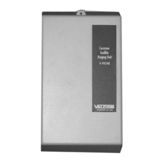
COMMON AUDIBLE RINGING UNIT
GENERAL
The Common Audible Ringing Unit provides an
audible signal over the paging system when there is
an incoming call. It is used between a telephone
system and the public address system.
SPECIFICATIONS
Activation
•
1A2 Bell/Buzzer ICM
•
PABX Station Port
•
Electronic Key System Station Port
•
Contact Closure
Features
•
Activates via ringing voltage, buzzer voltage or
contact closure
•
Capable of switching signal to three zones
simultaneously
•
Uses standard 1A2 key system voltages
•
Each zone is equipped with a 5 Watt amplifier
and volume control
•
Contains a punchdown block as part of the unit
•
Compact size, can be mounted on wall or in
cabinet
•
Automatically switches paging speakers from
paging system to audible signal of the V-9924B
during the ring interval of the incoming call
•
Variable pitch control
•
Two auxiliary contact closures
Other Materials Required
•
-24VDC power supply
•
Cat 3 or 5 twisted pair telephone cable
•
Mounting screws and hardware
V-9924B
Dimensions/Weight
•
8.20" H x 4.55" W x 2.30" D
(20.83cm H x 11.56cm W x 5.84cm D)
•
1.3 lbs. (.59kg)
Power Requirements
The V-9924B requires a -24VDC "B" battery and
draws 50mA idle and 300mA maximum operating.
Signal Requirements
The V-9924B requires interrupted ringing or buzzer
voltage or dry contact closure to operate. The output
of the V-9924B will follow the interruptions of the
input. The ringing voltage should be approximately
105VAC and the current requirement would be 8mA.
The buzzer voltage should be approximately 18VAC
and the current requirement would be 10mA. The
V-9924B pulls approximately 3mA through a dry
contact closure for activation. Ringing and buzzer
voltages cannot be applied simultaneously. Use only
one method of activation.
1
Issue 6
947924
Advertisement
Table of Contents

Summary of Contents for Valcom V-9924B
-
Page 1: Specifications
V-9924B voltage or dry contact closure to operate. The output during the ring interval of the incoming call of the V-9924B will follow the interruptions of the • Variable pitch control input. The ringing voltage should be approximately •... -
Page 2: Installation
SIG COMMON (Pin 11 or 26) and the other side of the pair to 105VAC SIG (Pin 13 or 28). The V-9924B can also be activated by connecting one side of a dry... -
Page 3: Operation
Generally, this control does not require adjustment (See Figure 2). Figure 4 shows a V-9924B simplified schematic. When the V-9924B is idle, 1T IN is shorted to 1T TECHNICAL ASSISTANCE OUT, 1R IN is shorted to 1R OUT, 2T IN is shorted... - Page 4 The V-9924B is not field repairable. Valcom Valcom, Inc. equipment contains no user serviceable parts inside. Valcom, Inc. maintains service facilities in Repair and Return Dept. Roanoke, VA. Should repairs be necessary, attach a 5614 Hollins Road Roanoke, VA 24019-5056...
- Page 5 This warranty is in lieu of and excludes all other warranties, expressed or implied and in no event shall Valcom, Inc. be liable for any anticipated profits, consequential damages, loss of time or other losses incurred by the buyer in connection with the purchase, operation, or use of the product.


Need help?
Do you have a question about the V-9924B and is the answer not in the manual?
Questions and answers