
Subscribe to Our Youtube Channel
Related Manuals for UNI-T UT60F


Summary of Contents for UNI-T UT60F
-
Page 1: Table Of Contents
Model UT60F/G: OPERATING MANUAL Table of Contents Page Title Overview Unpacking Inspection Safety Information Rules For Safe Operation International Electrical Symbols The multimeter Structure Rotary Switch Functional Button Display Symbols Measurement Ranges Measurement Operation DC Voltage Measurement AC Voltage Measurement... - Page 2 Model UT60F/G: OPERATING MANUAL Title Page Resistance Diode Test Continuity Test Capacitance Frequency Temperature Maintenance General Service Replacing the Battery Replacing the Fuses...
-
Page 3: Overview
To avoid electric shock or personal injury, read the "Safety Information" and "Rules for Safe Operation" carefully before using the Meter. Digital Multimeter Model UT60F/UT60G (hereafter referred to as “the Meter”) are 3 3/4 digits with steady operations, fashionable structure and highly reliable measuring instrument. -
Page 4: Unpacking Inspection
Model UT60F/G: OPERATING MANUAL Unpacking Inspection Open the package case and take out the Meter. Check the following items carefully to see any missing or damaged part: Item Description 1 piece English Operating Manual 1 pair Test Lead 1 pair... -
Page 5: Safety Information
Model UT60F/G: OPERATING MANUAL Safety Information This Meter complies with the standards IEC61010: in pollution degree 2, overvoltage category (CAT. III 1000V, CAT. IV 600V) and double insulation. CAT. III: Distribution level, fixed installation, with smaller transient overvoltages than CAT. IV CAT IV: Primary supply level, overhead lines, cable systems etc. -
Page 6: Rules For Safe Operation
Model UT60F/G: OPERATING MANUAL Rules For Safe Operation (1) Warning To avoid possible electric shock or personal injury, and to avoid possible damage to the Meter or to the equipment under test, adhere to the following rules: Before using the Meter inspect the case. Do not use the Meter if it is damaged or the case (or part of the case) is removed. - Page 7 Model UT60F/G: OPERATING MANUAL Rules For Safe Operation (2) Before measuring current, check the Meter’s fuses and turn off power to the circuit before connecting the Meter to the circuit. Replace the battery as soon as the battery indicator appears. With a low battery, the Meter might produce false readings that can lead to electric shock and personal injury.
-
Page 8: International Electrical Symbols
Model UT60F/G: OPERATING MANUAL International Electrical Symbols AC (Alternating Current). DC (Direct Current). AC or DC. Grounding. Double Insulated. Deficiency of Built-In Battery. Continuity Test. Diode. Fuse. Warning. Refer to the Operating Manual. Conforms to Standards of European Union. -
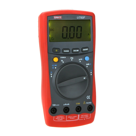
Page 9: The Multimeter Structure
4 HzV Input Terminal: Input for voltage, frequency, resistance,diode, capacitance and continuity measurements. 5 COM Input Terminal: Return terminal for all measurements. 6 Model UT60F: A mA Input Terminal; Input for A and mA measurement. Model UT60G: mA C Input Terminal Input for mA and temperature measurement. -
Page 10: Rotary Switch
Capacitance measurement Frequency measurement Temperature measurement (UT60G only) AC or DC current measurement range from 0.1 A to 4.000mA (UT60F only) Model UT60F: AC or DC current measurement range from 0.01mA to 400.0mA Model UT60G: AC or DC current measurement range from 0.01mA to 600.0mA. -
Page 11: Functional Button
Model UT60F/G: OPERATING MANUAL Functional Button(1) Below table indicated for information about the functional button operations. Button Measuring Operation Performed F u n c t i o n Press once to turn the Display Display Backlight on and it shall shut off... - Page 12 Model UT60F/G: OPERATING MANUAL Functional Button(2) Any rotary Press HOLD H to enter and exit Switch the Hold mode in any mode, the Position Meter beeps. HOLDH l Press and hold At OFF HOLD H button while turning position on the Meter to display full icons.
-
Page 13: Display Symbols
Model UT60F/G: OPERATING MANUAL Display Symbols(1) (see figure 2) 232C n mF 10/11 Mk Hz 12/13 ( figure 2) Number Symbol Meaning Indicator for DC voltage or current Indicator for AC voltage or current The Meter is in the auto range... - Page 14 Model UT60F/G: OPERATING MANUAL Display Symbols(2) (see figure 2) Amperes (amps). The unit of current. A,mA mA: Milliamp, 1x10 or 0.001 amperes. A:Microamp.1x10 or 0.000001 amperes. Volts. The unit of voltage. mV, V mV: Millivolt. 1x10 or 0.001 volts :Ohm. The unit of resistance.
-
Page 15: Measurement Ranges
Model UT60F/G: OPERATING MANUAL Measurement Ranges(1) A measurement range determines the highest value the Meter can measure. Most Meter functions have more than one range. See “Accuracy Specifications.” A. Selecting a Measurement Range Being in the right measurement range is important: l If the range is too low for the input, the Meter displays OL to indicate an overload. - Page 16 Model UT60F/G: OPERATING MANUAL Measurement Ranges(2) The Meter returns to the autorange mode and displayed. Note l If you manually change the measurement range after entering the Hold recording modes, the Meter exits these modes.
-
Page 17: Measurement Operation
1000V, although readings may be obtained. The DC Voltage ranges are: Model UT60F: 400mV, 4V, 40V, 400V and 1000V; Model UT60G: 600mV, 6V, 60V, 600V and 1000V. To measure DC voltage, connect the Meter as follows: Insert the red test lead into the HzV terminal and the black test lead into the COM terminal. -
Page 18: Ac Voltage Measurement
1000V rms, although readings may be obtained. The AC Voltage ranges are: Model UT60F: 400mV,4V,40V,400V and 1000V; Model UT60G: 600mV, 6V, 60V, 600V and 1000V. To measure AC voltage, connect the Meter as follows: 1. Insert the red test lead into the HzV terminal and... -
Page 19: Dc Or Ac Current Measurement
Model UT60F/G: OPERATING MANUAL Measurement Operation(3) and press BLUE button 2. Set the rotary switch to V to select AC measurement mode. 3. Connect the test leads across with the object being measured. The measured value shows on the display. - Page 20 A To measure current, do the following: 1. Model UT60F: Insert the red test lead into the AmA or 10A terminal and the black test lead into the COM terminal. Model UT60G: Insert the red test lead into the C or 10A terminal and the black test lead into the COM terminal.
-
Page 21: Measuring Resistance
The resistance ranges are: Model UT60F: 400 , 4k , 40k , 400k , 4M , and 40M . Model UT60G: 600 , 6k , 60k , 600k , 6M , and 60M . To measure resistance, connect the Meter as follows: 1. - Page 22 Note: l The test leads can add 0.1 to 0.2 of error to resistance measurement. To obtain precision readings in low-resistance measurement (UT60F: 400 and UT60G is 600 ), short-circuit the input terminals beforehand and record the reading obtained (called this reading as X).
-
Page 23: Testing Diodes
Model UT60F/G: OPERATING MANUAL Measurement Operation(7) E.Testing Diodes (see figure 7) Select black ( figure 7) Warning To avoid harms to you, please do not attempt to measure voltages higher than 60V DC or 30V rms AC. To avoid damages to the Meter or to the devices under test, disconnect circuit power and discharge all the high-voltage capacitors before testing diodes. -
Page 24: Testing For Continuity
Model UT60F/G: OPERATING MANUAL Measurement Operation(8) Note l In a circuit, a good diode should still produce a forward voltage drop reading of 0.5V to 0.8V; however, the reverse voltage drop reading can vary depending on the resistance of other pathways between the probe tips. - Page 25 Model UT60F/G: OPERATING MANUAL Measurement Operation(9) Warning To avoid harms to you, please do not attempt to measure voltages higher than 60V DC or 30V rms AC. To avoid damages to the Meter or to the devices under test, disconnect circuit power and discharge all the high-voltage capacitors before measuring continuity.
-
Page 26: Capacitance Measurement
Use the DC votage function to confirm that the capacitor is discharged. The Meter capacitance ranges are: Model UT60F: 4nF, 40nF, 400nF, 4 F, 40 F, 400 F and 4mF. Model UT60G: 6nF, 60nF, 600nF, 6 F, 60 F, 600 F and 6mF. -
Page 27: Frequency Measurement
Model UT60F/G: OPERATING MANUAL Measurement Operation(11) Note l For testing the capacitor with polarity, connect the red test lead or red clip to anode & black test lead or black clip to cathode. l To minimize the effect of capacitance stored in the test leads, the test lead should be as short as possible. - Page 28 Model UT60F/G: OPERATING MANUAL Measurement Operation(12) The measurement ranges are: Model UT60F: 4kHz, 40kHz, 400kHz, 4MHz and 40MHz. Model UT60G: 6kHz, 60kHz, 600kHz, 6MHz and 60MHz. To measure frequency, connect the Meter as follows: 1. Insert the red test lead into the HzV terminal and the black test lead into the COM terminal.
-
Page 29: Model Ut60 G: Temperature Measurement
Model UT60F/G: OPERATING MANUAL Measurement Operation(13) I. Model UT60 G: Temperature Measurement (see figure 11) ( figure 11) Warning To avoid harms to you, please do not attempt to measure voltages higher than 60V DC or 30V rms AC. The temperature measurement range is -40... -
Page 30: Sleep Mode
Model UT60F/G: OPERATING MANUAL Sleep Mode To preserve battery life, the Meter automatically turns off if you do not turn the rotary switch or press any button for around 10 minutes. The Meter can be activated by turning the rotary switch or pressing any button except the YELLOW button. -
Page 31: General Specifications
Model UT60F/G: OPERATING MANUAL General Specifications l Maximum Voltage between any Terminals and Grounding : 1000V rms. Fused Protection for AmA Input Terminal : Model UT60F : 0.5A, 250V, fast type fuse, ø5×20mm Fused Protection for C Input Terminal : Model... -
Page 32: Accuracy Specifications
Model UT60F/G: OPERATING MANUAL Accuracy Specifications(1) Accuracy: (a% reading + b digits), guarantee for 1 year. Operating temperature: 18 C~28 Relative humidity: Temperature coefficient:0.1×(specified accuracy)/1 A. DC Voltage Range Resolution Accuracy UT60F UT60G 600.0mV 0.1mV 400.0mV (0.5%+5) 6.000V 4.000V (0.5%+3) 10mV 60.00V... -
Page 33: Dc Current
10.00A 10mA (1.5%+5) Remarks l Overload protection: Model UT60F at 400.0 A to 400.0mA range: 0.5A, 250V, fast type fuse, ø5×20mm Model UT60F at 10.00A range: 10A, 250V, fast type fuse, ø5×20mm Model UT60G at 60.00mA to 600.0mA range: 1A, 250V, fast type fuse, ø5×20mm Model UT60G at 10.00A range:... -
Page 34: Resistance
Model UT60F/G: OPERATING MANUAL Accuracy Specifications(3) Model UT60F at 10.00A range: 10A, 250V, fast type fuse, ø5×20mm Model UT60G at 60.00mA to 600.0mA range: 1A, 250V, fast type fuse, ø5×20mm Model UT60G at 10.00A range: 10A, 250V, fast type fuse, ø5×20mm l At 10.00A range:... -
Page 35: Capacitance
Model UT60F/G: OPERATING MANUAL Accuracy Specifications(4) H. Capacitance Range Overload Resolution Accuracy Protection UT60F UT60G 4.000nF 6.000nF (4%+10) 40.00nF 60.00nF 10pF 400.0nF 600.0nF 100pF (4%+3) 4.000 F 6.000 F 600Vp 60.00 F 40.00 f 10nF 400.0 F 600.0 F 100nF (5%+10) 4.000mF... -
Page 36: Maintenance
Model UT60F/G: OPERATING MANUAL Maintenance(1) This section provides basic maintenance information including battery and fuse replacement instruction. Warning Do not attempt to repair or service your Meter unless you are qualified to do so and have the relevant calibration, performance test, and service information. -
Page 37: Replacing The Fuses
Model UT60F/G: OPERATING MANUAL Maintenance(2) Warning To avoid false readings, which could lead to possible electric shock or personal injury, replace the battery as soon as the battery indicator “ ” appears. Make sure the test leads are disconnected from the circuit being tested before opening the case bottom. - Page 38 Model UT60F/G: OPERATING MANUAL Maintenance(3) Warning To avoid electrical shock or arc blast, or personal injury or damage to the Meter, use specified fuses ONLY in accordance with the following procedure. To replace the Meter’s fuse: l Press the POWER to turn the Meter off and remove all connections from the terminals.
- Page 39 Model UT60F/G: OPERATING MANUAL RS232C Serial Port(1) A. RS232C Port Cable Computer Meter D-sub D-sub D-sub Pin Name 9 Pin 25 Pin 9 Pin Female Female Male B. Setting of RS232C Serial Ports Default of RS232C Serial Port for communication is set as:...
- Page 40 Model UT60F/G: OPERATING MANUAL RS232C Serial Port(2) l Can access to a local or a network CD-ROM l A free serial port l A mouse or other pointing device supported by Windows. Please refer to the included CD-ROM “Installation Guide & Computer Interface Software” for installing and operating instructions of the Interface Program.
- Page 41 Model UT60F/G: OPERATING MANUAL...
- Page 42 Model UT60F/G: OPERATING MANUAL Copyright 2001 Uni-Trend International Limited. All rights reserved. Manufacturer: UNI-TREND TECHNOLOGY(DONG GUAN)LIMITED Address: Dong Fang Da Dao, Bei Shan Dong Fang Industrial Development District, Hu Men Town, Dong Guan City, Guang Dong Province, China Headquarters: Uni-Trend International Limited...
Need help?
Do you have a question about the UT60F and is the answer not in the manual?
Questions and answers