Table of Contents
Advertisement
Available languages
Available languages
Advertisement
Chapters
Table of Contents

Subscribe to Our Youtube Channel
Related Manuals for UNI-T UT61B


Summary of Contents for UNI-T UT61B
- Page 1 ® UT61B MANUAL HANDLEIDING MODE D’EMPLOI...
- Page 2 ® UT61B ODERN IGITAL ULTIMETER • Illustrations and tables • English Operating Manual • Nederlandse handleiding • Mode d’ emploi français LLUSTRATIONS FIG 1: The meter’s structure FIG 2: voltage measurement FIG 3: AC/DC current Measurement FIG 4: Resistance Measurement FIG 5: Diode measurement...
- Page 3 Model: UT61B MANUAL ABLES Accuracy: +/-(a% reading + b digits) - guaranteed for 1 year Operating temperature: 23°C +/- 5% Relative Humidity: < 75% DC V OLTAGE Range Resolution Accuracy 40mV 0,01mV +/-(0.8%+3) 400mV 0.1mV 0.001V 0.01V +/-(0.5%+1) 400V 0.1V 1000V +/-(1.0%+3)
- Page 4 ® DC C URRENT Range Resolution Accuracy Overload protection 400µA 0,1µA +/-(1%+2) 4000µA 1µA Fuse: 1A / 250V Fast type 6x25mm 40mA 0.01mA +/-(1.2%+3) 400mA 0,1mA 0.001mA Fuse: 10A /250V +/-(1.5%+5) Fast type: 6x25mm 0.01A When <5A: continuous measurement is allowed When >5A: continuous measurement less than 10 seconds at an interval more than 15 minutes AC C URRENT...
-
Page 5: Broken Circuit Is Around > 35W, The Buzzer Does Not Beep. Good Circuit Resistance Value Is
Model: UT61B MANUAL APACITANCE Range Resolution Accuracy 40nF 0.01nF 400nF 0.1nF +/-(3%+5) 4µF 0.001µF 40µF 0.01µF 400µF 0.1µF +/-(4%+5) 4000µF 1µF unspecifi ed There is around 10nF residual reading when the circuit is open REQUENCY Range Resolution Accuracy 10Hz 0.01Hz 100Hz 0.1Hz... - Page 6 ® EMPERATURE Range Resolution Accuracy °C 1°C (-40° ~ -20°C): -(8%+5) (-20° ~ 0°C): +/-(1.5%+4) (0° ~ 100°C): +/-(1.2%+3) (100° ~ 1000°C): +/-(2.5%+2) °F 1°F (-40°F ~4°F): -(8%+6) (4°F ~32°F): +/-(1.2%+5) (32°F ~212°F): +/-(1.2%+4) (212°F ~1832°F): +/-(2.5%+3) Broken circuit is around > 35W, the buzzer does not beep. Good circuit resistance value is < 10, the buzzer beeps continuously.
-
Page 7: Table Of Contents
Model: UT61B MANUAL ONTENTS • Overview • Unpacking inspection • Safety information • International electrical symbols • The meter structure • General specifi cations • Functional buttons • Measurement operation AC/DC voltage measurement AC/DC current measurement Resistance measurement Continuity measurement... -
Page 8: Overview
This operating manual covers information on safety and cautions. Please read the relevant information carefully and observe all the Warnings and Notes strictly. Digital multimeter model UT61B is an auto ranging multimeter. The meter can measure AC/ DC Voltage and Current, Resistance, Diode, Continuity buzzer, Capacitance, Frequency, and temperature. -
Page 9: International Electrical Symbols
Model: UT61B MANUAL • Do not use or store the meter in an environment of high temperature and humidity. The performance of the meter may deteriorate after dampened. • Disconnect circuit power and discharge all high voltage capacitors before testing resistance, continuity and diodes. -
Page 10: The Meter Structure
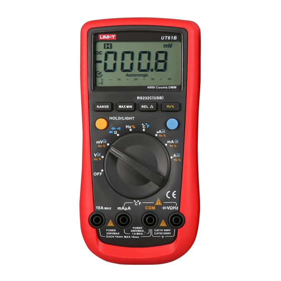
® ETER TRUCTURE See fi gure 1 LCD Display Functional Buttons Blue button Rotary Switch Input terminal ENERAL PECIFICATIONS 1. Maximum voltage between any terminals and grounding. Refer to different range input protection voltage. 2. 10A terminal: 10A H 250V Fast Type Ceramic Fuse 6x25mm. 3. -
Page 11: Functional Buttons
DC and AC measurement mode. 3. Connect the test leads across with the object being measured. The measured value shows on the display. UT61B displays effective value of sine wave (mean value re- sponse). In each range, the meter has an input impedance of 10M. This loading effect can cause measurement errors in high impedance circuits. -
Page 12: Ac/Dc Current Measurement
® B. DC/AC Current Measurement (See fi gure 3) Before connecting the meter to the return circuit to be tested, cut off the current of the circuit. If the fuse burns down during measurement, the meter may be damaged or the operator himself may be hurt. -
Page 13: Continuity Measurement
Model: UT61B MANUAL Note • The test leads cause 0.2~0.5 resistance variation during the measurement, In order to obtain precision readings in low-resistance measurement, need to make the short circuit on the test leads and mark the measurement value which show on LCD display. -
Page 14: Capacitance Measurement
® For forward drop readings on any semiconductor component place the red test lead on the components anode and the black on the components cathode. The measured value shows on the display. • In a circuit, a good diode should still produce a forward voltage drop reading of 500 ~ 800mV. -
Page 15: Temperature Measurement
Model: UT61B MANUAL The measured value shows on the display. If you need to measure duty cycle, press Hz% button to select % measurement. Note: • Input amplitude: When 10Hz~10MHz: 300mV < a < 30Vrms H. Temperature measurement (see fi gure 9) The included K type point contact temperature probe can only be used in the measurement below 230°C. -
Page 16: Maintenance And Service
® AINTENANCE ERVICE Do not attempt to repair or service your meter unless you are qualifi ed to do so and have the relevant calibration, performance test and service information. A. General Service and Maintenance • Periodically wipe the case with a damp cloth and mild detergent. Do not use abrasives or solvents. - Page 17 Model: UT61B HANDLEIDING NHOUD • Overzicht • Nazicht van de verpakking • Veiligheidsinformatie • International elektrische symbolen • Lay out van de meter • Algemene specifi caties • Functietoetsen • Metingen Gelijk- en wisselspanningsmeting 20 Gelijk- en wisselstroommeting Weerstandsmeting Continuïteitstest...
-
Page 18: Overzicht
Deze handleiding bevat alle veiligheidsvoorschriften en voorzorgsmaatregelen. Gelieve de handleiding aandachtig en hou rekening met alle waarschuwen en notities. De digitale multimeter model UT61B is een auto range multimeter. Het toestel meet AC/ DC spanning en stroom, weerstand, diode, Continuïteit, capaciteit, frequentie en temper- atuur. -
Page 19: International Elektrische Symbolen
Model: UT61B HANDLEIDING • Vervang de batterij wanneer de indicator voor lage batterijspanning op het LCD scherm verschijnt: “ ”. Een lage batterij kan foute metingen als resultaat hebben, wat op zijn beurt kan leiden tot elektrische schokken of kwetsuren. -
Page 20: Lay Out Van De Meter
® UT VAN HET OESTEL Zie fi guur 1 LCD Display Functie toetsen Blauwe toets Draaischakelaar Ingangsbussen LGEMENE PECIFICATIES 1. Maximale voltage tussen ingangsbussen en aarding - zie ingangsvoltage verschillende bereiken. 2. 10A meetbus: 10A H 250V Fast Type Ceramic Fuse 6x25mm. 3. -
Page 21: Functietoetsen
Model: UT61B HANDLEIDING UNCTIE OETSEN 1. LIGHT toets Druk deze toets gedurende 2 seconden om de backlight te activeren of desactiveren. Na ca. 10 seconden gaat de verlichting automatisch uit. 2. HOLD toets Druk de HOLD toets om de HOLD functie in of uit te schakelen. De HOLD functie is te gebruiken bij alle meetfuncties behalve frequentie meting. -
Page 22: Gelijk- En Wisselstroommeting
® Nota: • In elk bereik is de ingangsimpedantie ongeveer 10M. Deze impedantie kan de meetwaarde beïnvloeden in circuits met een hoge impedantie. Bij circuits met een impedantie kleiner of gelijk aan 10k, is de foutmarge verwaarloosbaar (0.1% of minder). •... -
Page 23: Continuïteitstest
Model: UT61B HANDLEIDING Nota’s: • Als de weerstand over draden beschikt, kan u gebruik maken van de multi purpose connector om de meting uit te voeren. • De testsnoeren zorgen voor verhoging van de weerstandswaarde met 0.2~0.5. Bij lage weerstandsmetingen dient men de weerstandswaarde van de meetsnoeren af te trekken van de gemeten weerstandswaarde. -
Page 24: Diodetest
® E. Diodetest (Zie fi guur 5) Schakel de stroom van het te testen circuit uit en ontlaadt alle hoogspannings conden- satoren, om schade te voorkomen aan het meettoestel of te testen circuit. Het is aan te raden geen metingen uit te voeren bij spanningen hoger dan DC 60V of AC 30V. 1. -
Page 25: Frequentie Meting
Model: UT61B HANDLEIDING • Bij grote capaciteiten (>100µF) kan het enige tijd duren alvorens een stabiele waarde te verkrijgen. • Het LCD display geeft “OL” weer als de capaciteit kortgesloten is of groter is dan het maximale bereik van het toestel. -
Page 26: Data Output
® UTPUTTING • Druk gedurende 2 seconden op de REL toets om de RS232C uitgang of USB modus te activeren. • De slaap modus wordt uitgeschakeld als u de RS232C of USB functie hebt geac- tiveerd, het slaap symbool op het scherm zal verdwijnen. •... -
Page 27: Vervangen Van De Zekeringen
Model: UT61B HANDLEIDING Hoe de batterij vervangen: 1. Schakel de meter uit en maak de meetsnoeren los van het toestel. 2. Gebruik een schroevendraaier om de schroefjes van het batterij compartiment los te maken. De batterij kan vervolgens eenvoudig vervangen worden. - Page 28 ® ONTENU • Vue d’ensemble • Inspection de l’emballage • Consignes de sécurité • Symboles électriques internationaux • Structure du multimètre • Spécifi cations générales • Boutons de fonctionnement • Mesures A. Mesure de tension AC/DC B. Mesure de courant AC/DC C.
-
Page 29: Vue D'ensemble
Veuillez lire les notices attentativement et prendre note de toutes les consignes de sécurités. Le multimètre UT61B est un instrument digital auto range. Mesure de tension AC/DC, cou- rant AC/DC, Résistance, capacité, fréquence et température, diode et teste de continuité. -
Page 30: Symboles Électriques Internationaux
® • Remplacer la pile dès que le voyant de batterie apparaît. Si la pile est trop faible, les relevés risquent d’être faussés et vous vous exposez à des chocs électriques ou à des blessures. • Ne pas utiliser ni stocker l’appareil en environnement humide, explosif ou infl amma- ble, ni en cas de températures élevées ou de champ magnétique puissant. -
Page 31: Structure Du Multimètre
Model: UT61B MODE D’EMPLOI TRUCTURE DU ULTIMETRE Voire fi gure 1 1. Affi chage LCD 2. Bouton de fonction 3. Bouton bleu 4. Bouton rotatif 5. Bornes d’entrée PECIFICATIONS ENERALES 1. 10A borne d’entrée: 10A H 250V Fusible Type Rapide 6x25mm. -
Page 32: Boutons De Fonctionnement
® OUTONS DE ONCTIONNEMENT 1. Bouton LIGHT Appuyer le bouton jaune (LIGHT) pendant 2 sec pour activer ou désactiver le rétro éclairage. 2. Bouton HOLD Appuyer le bouton HOLD pour activer ou désactiver la fonction HOLD. IL est pos- sible d’utiliser la fonction pour toutes les fonctions de mesurage sauf mesurage de fréquence. -
Page 33: Mesure De Courant Ac/Dc
Model: UT61B MODE D’EMPLOI Note: Pour éviter l’endommagement de l’appareil, il est conseillé de ne pas mesurer des tensions plus élevées de 500V. B. Mesure de courant DC/AC (Voire fi gure 3) Avant de connecter le multimètre avec le circuit à tester, il faut débrancher le circuit. Si le fusible saute pendant la mesure, le multimètre peut être endommagé... -
Page 34: Test De Continuité
® Note • Les fi ls test peuvent ajouter de 0.1~0.2 d’erreur de mesure de résistance. Pour obtenir des lectures de précision dans les mesures de basses résistances, il faut court- circuitez les bornes d’entrée à l’avance et enregistrer les résultats obtenus. C’est la résistance additionnelle du fi... -
Page 35: Mesure De Capacité
Model: UT61B MODE D’EMPLOI 3. Puis connecter le fi l rouge avec l’anode de la diode et le fi l noir avec le cathode de la diode. Le test de diode envoie un courant au travers de la jonction des semi-conduc- teurs, et puis mesure la chute de tension à... -
Page 36: Mesure De Température
® Si on veut sélectionner le duty cycle, appuyer le bouton Hz% pour changer la fonction. Note: Amplitude d’entrée: a Quand 10Hz ~100MHz: 300mV < a < 30V rms H. Mesure de température (voire fi gure 9) La probe de température type K, peut seulement être utilisé pour des mesures de tempéra- tures sous 230°C. -
Page 37: Mode De Reveillement
Model: UT136B MODE D’EMPLOI EVEILLEMENT Afi n de prolonger la durée de vie de la batterie, le mètre se mets automatiquement dans le mode de reveillement quand aucune activité est effectué pendant 15 minutes. Il est possible de réactiver le multimètre par appuyer n’importe quel bouton. Pour désacitver la fonction de reveillement, il faut appuyer le bouton BLEU quand le multimètre est branché. - Page 38 ® Disposal of Old Electronic Equipment. Applicable to EU and other European countries with separate collection systems. This symbol on the product or on its packaging indicates that this product shall not be treated as household waste. Instead it shall be handed over to the applicable collection point for recycling of electronic equipment.
- Page 39 ® OHMERON BVBA LEO DE BETHUNELAAN 101 9300 AALST WWW.OHMERON.COM...
Need help?
Do you have a question about the UT61B and is the answer not in the manual?
Questions and answers