
Related Manuals for UNI-T UT601


Summary of Contents for UNI-T UT601
-
Page 1: Table Of Contents
Model UT601: OPERATING MANUAL Table of Contents Title Page Overview Unpacking Inspection Safety Information Rules For Safe Operation International Electrical Symbols The Meter Structure Functional Buttons Display Symbols Measurement Operation A. Measuring Resistance B. Capacitance Measurement C. Diode and Continuity Test D. - Page 2 Model UT601: OPERATING MANUAL...
-
Page 3: Overview
To avoid electric shock or personal injury, read the “Safety Information” and “Rules for Safety Operation” carefully before using the Meter. Digital Capacitance Meter Model UT601 (hereafter referred to as “the Meter”) is a 3 1/2 digits with steady operations, fashionable design and highly reliable hand-held measuring instrument. -
Page 4: Unpacking Inspection
Model UT601: OPERATING MANUAL Unpacking Inspection Open the package case and take out the Meter. Check the following items carefully to see any missing or damaged part: Item Description English Operating Manual 1 piece Test Clip 1 pair 9V Battery (NEDA1604, 6F22 or 006P) -
Page 5: Safety Information
Model UT601: OPERATING MANUAL Safety Information This Meter complies with the standards EMC EN61326. Use the Meter only as specified in this operating manual, otherwise the protection provided by the Meter may be impaired. In this manual, a Warning identifies conditions and actions that pose hazards to the user, or may damage the Meter or the equipment under test. -
Page 6: Rules For Safe Operation
Model UT601: OPERATING MANUAL Rules For Safe Operation Warning To avoid possible electric shock or personal injury, and to avoid possible damage to the Meter or to the equipment under test, adhere to the following rules: Before using the Meter inspect the case. Do not use the Meter if it is damaged or the case (or part of the case) is removed. - Page 7 Model UT601: OPERATING MANUAL When servicing the Meter, use only the same model number or identical electrical specifications replacement parts. The internal circuit of the Meter shall not be altered at will to avoid damage of the Meter and any accident.
-
Page 8: International Electrical Symbols
Model UT601: OPERATING MANUAL International Electrical Symbols Grounding Double Insulated Deficiency of Built-In Battery. Continuity Test. Diode. Capacitance Test Fuse. Warning. Refer to the Operating Manual. Conforms to Standards of European Union. -
Page 9: The Meter Structure
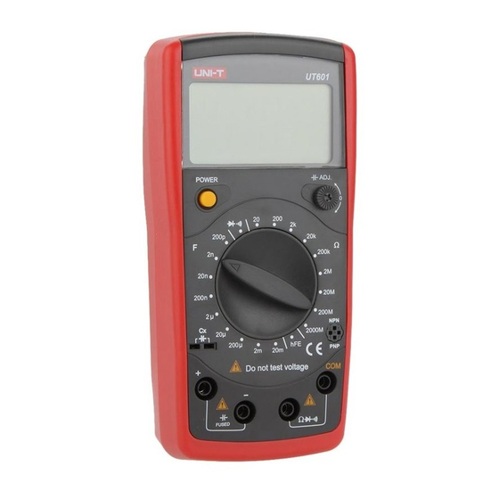
Model UT601: OPERATING MANUAL The Meter Structure (see figure 1) (figure 1) 1. LCD Display 2. Capacitance Zero Adjustment Switch 3. Transistor Jack 4. Resistance, Diode and Continuity Buzzer Input Terminal 5. Capacitance Input Terminal 6. Small Value Capacitance Jack 7. -
Page 10: Display Symbols
Model UT601: OPERATING MANUAL Display Symbols (see figure 2) µF (figure 2) No. Symbol Meaning Data hold is active. The battery is low. Warning: To avoid false readings, which could lead to possible electric shock or personal injury, replace the battery as soon as the battery indicator appears. -
Page 11: Measurement Operation
Model UT601: OPERATING MANUAL Measurement Operation Make sure the Low Battery Display is not on, otherwise false readings may be provided. Pay extra attention to the symbol, before carrying measurement, which is located besides the input terminals of the Meter. - Page 12 Model UT601: OPERATING MANUAL Note When measuring at 20 and 200 range, the test clips can add 0.1 to 0.3 error to resistance. To obtain precise readings in these low-resistance measurement, that is the range 20 and 200 short circuit the input terminals beforehand and record the reading obtained (called this reading as X).
-
Page 13: Capacitance Measurement
Model UT601: OPERATING MANUAL B. Capacitance Measurement (see figure 4) (figure 4) Warning To avoid damage to the Meter or to the equipment under test, disconnect circuit power and discharge all high-voltage capacitors before measuring capacitance. Use the DC Voltage function to confirm that the capacitor is discharged. - Page 14 Model UT601: OPERATING MANUAL When measuring small value capacitor, that is 200pF, 2nF and 20nF, first open circuit the test clips or the Small Value Capacitance Jack, then turn the Capacitance Zero Adjustment Switch to adjust zero. The measured value shows on the display.
-
Page 15: Diode And Continuity Test
Model UT601: OPERATING MANUAL C. Diode and Continuity Test (see figure 5) (figure 5) Warning To avoid damages to the Meter or to the devices under test, disconnect circuit power and discharge all the high-voltage capacitors before measuring diodes and continuity. - Page 16 Model UT601: OPERATING MANUAL Note In a circuit, a good diode should still produce a forward voltage drop reading of 0.5V to 0.8V; however, the reverse voltage drop reading can vary depending on the resistance of other pathways between the probe tips.
-
Page 17: Transistor Hfe Measurement
Model UT601: OPERATING MANUAL D. Transistor hFE Measurement (see figure 6) (figure 6) To measure transistor, set up the Meter as follows: Check that the transistor is PNP or NPN type. Insert the transistor to be measured to the corresponding Transistor Jack. -
Page 18: General Specifications
Model UT601: OPERATING MANUAL General Specifications Fused Protection for capacitance Input Terminal: 0.315A, 250V, fast type fuse, 5x20 mm. Maximum Display: Display: 1999. Measurement Speed: Updates 2-3 times /second. Polarity: Auto. (Display “-“ when negative) Overloading: Display “1” Range: Manual Ranging... -
Page 19: Accuracy Specifications
Model UT601: OPERATING MANUAL Accuracy Specifications Accuracy: (a% reading + b digits), guarantee for 1 year. Operating temperature: 23 Relative humidity: <75%. Temperature coefficient: 0.1 x (specified accuracy) / 1 A. Resistance Test Overload Range Resolution Accuracy Protection 0.01 (1%+5) (0.8%+3) -
Page 20: Capacitance Test
Model UT601: OPERATING MANUAL B. Capacitance Test Testing Range Resolution Accuracy Frequency 200.0pF 0.1pF 2.000nF 0.001nF 800Hz 20.00nF 0.01nF 200.0nF 0.1nF (0.5%+10) 2.000µF 0.001µF 80Hz 20.00µF 0.01µF 200.0µF 0.1µF 2.000mF 0.001mF (2%+2) 20.00mF 0.01mF Remarks: Overload Protection 0.315A, 250V, fast type fuse, 5x20 mm... -
Page 21: Transistor
Model UT601: OPERATING MANUAL D. Transistor Testing Overload Range Resolution Condition Protection 2.8V 250V rms I bo 10µA Remarks: The display value is the tested transistor’s nearest value (0~1000 ). -
Page 22: Maintenance
Model UT601: OPERATING MANUAL Maintenance This section provides basic maintenance information including battery and fuse replacement instruction. Warning Do not attempt to repair or service your Meter unless you are qualified to do so and have the relevant calibration, performance test, and service information. -
Page 23: Replacing The Battery
Model UT601: OPERATING MANUAL B. Replacing the Battery (see figure 7) (figure 7) Warning To avoid false readings, which could lead to possible electric shock or personal injury, replace the battery as soon as the battery indicator “ ” appears. -
Page 24: Replacing The Fuse
Model UT601: OPERATING MANUAL C. Replacing the Fuse (see figure 8) (figure 8) Warning To avoid electrical shock or arc blast, or personal injury or damage to the Meter, use specified fuses ONLY in accordance with the following procedure. To replace the Meter’s fuse: Turn the Meter power off and remove all connections from the terminals. - Page 25 Model UT601: OPERATING MANUAL Replacement of the fuses is seldom required. Burning of a fuse always results from improper operation. ** END **...
- Page 26 Model UT601: OPERATING MANUAL Copyright 2005 Uni-Trend Group Limited. All rights reserved. Manufacturer: Uni-Trend Technology (Dongguan) Limited Dong Fang Da Dao Bei Shan Dong Fang Industrial Development District Hu Men Town, Dongguan City Guang Dong Province China Postal Code: 523 925...
Need help?
Do you have a question about the UT601 and is the answer not in the manual?
Questions and answers