
Related Manuals for Campbell Bowen Ratio Instrumentation


Summary of Contents for Campbell Bowen Ratio Instrumentation
- Page 1 Bowen Ratio Instrumentation Revision: 9/05 C o p y r i g h t ( c ) 1 9 8 7 - 2 0 0 5 C a m p b e l l S c i e n t i f i c ,...
- Page 2 CAMPBELL SCIENTIFIC, INC. CAMPBELL SCIENTIFIC, INC. will return such products by surface carrier prepaid. This warranty shall not apply to any CAMPBELL SCIENTIFIC, INC. products which have been subjected to modification, misuse, neglect, accidents of nature, or shipping damage. This warranty is in lieu of all other warranties, expressed or implied, including warranties of merchantability or fitness for a particular purpose.
-
Page 3: Table Of Contents
Bowen Ratio Table of Contents PDF viewers note: These page numbers refer to the printed version of this document. Use the Adobe Acrobat® bookmarks tab for links to specific sections. 1. System Overview ............1-1 1.1 Review of Theory ................. 1-1 1.2 System Description................ - Page 4 Bowen Ratio Table of Contents Figures 1.2-1. Vapor Measurement System............. 1-3 1.2-2. Thermocouple Configuration............1-4 2-1. CSI Bowen Ratio System ..............2-2 2.2-1. Placement of Thermocouples and Heat Flux Plates ......2-3 2.2-2. TCAV Spatial Averaging Thermocouple Probe......2-4 2.3. A block diagram for the connections between the datalogger, the BR relay driver and components, and the external battery....
-
Page 5: System Overview
Section 1. System Overview 1.1 Review of Theory By analogy with molecular diffusion, the flux-gradient approach to vertical transport of an entity from or to a surface assumes steady diffusion of the entity along its mean vertical concentration gradient. When working within a few meters of the surface, the water vapor and heat flux densities, E and H, may be expressed as: ∂ρ... - Page 6 Section 1. System Overview − β λε − λε is the psychrometric constant. where PC The surface energy budget is given by, − − − = 0 , G H L where R is net radiation for the surface and G is the total soil heat flux. The sign convention used is R positive into the surface and G, H, and L positive...
-
Page 7: System Description
The position of the two psychrometers is periodically reversed to cancel systematic sensor errors (Suomi, 1957; Fuchs and Tanner, 1970). In the Campbell Scientific system, vapor concentration is measured with a single cooled mirror dew point hygrometer , using a technique developed for multiple level gradient studies (Lemon, 1960). -
Page 8: Air Temperature Measurement
Section 1. System Overview A datalogger is used to measure all sensors and control the valve that switches the air stream through the cooled mirror. The resolution of the dewpoint temperature measurement is ±0.003°C over a ±35°C range. The limitation is the stability of the Dew-10, approximately 0.05°C, yielding better than ±0.01 kPa vapor pressure resolution over most of the environmental range. -
Page 9: Net Radiation And Soil Heat Flux
Section 1. System Overview the gradient measurement is due only to the difference in the radiative heating of the two TC junctions and their physical symmetry minimizes this. Conversely, contamination of only one junction can cause larger errors. Applying temperature gradients to the TC connectors was found to cause offsets. - Page 10 Section 1. System Overview This is a blank page.
-
Page 11: Station Installation
0.5 to 3 meters. The mounting arms should be oriented due south to avoid partial shading of the thermocouples. The net radiometer is mounted on a separate stake (not provided by Campbell Scientific) so that the tripod is not a significant portion of its field of view. It should be positioned so that it is never shaded by the tripod or mounting arms and should be mounted so that it points south. -
Page 12: Soil Thermocouples And Heat Flux Plates
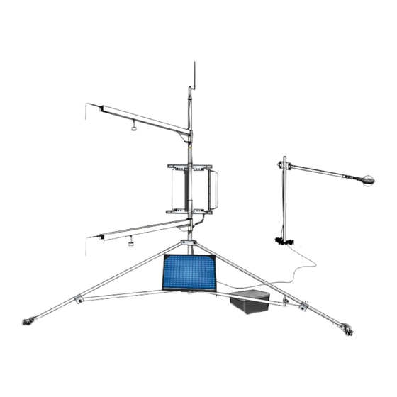
Section 2. Station Installation Q7-BR (system) FIGURE 2-1. CSI Bowen Ratio System 2.2 Soil Thermocouples and Heat Flux Plates The soil thermocouples and heat flux plates are typically installed as shown in Figure 2.2-1. The TCAV parallels four thermocouples together to provide the average temperature, as shown in Figure 2.2-2). -
Page 13: Placement Of Thermocouples And Heat Flux Plates
Section 2. Station Installation To minimize thermal conduction down the sensor lead wires, they should be buried for a short distance back from the sensor. In particular, do not run the leads directly to the surface, but wrap them around the edge of the hole, keeping the leads at the same level as the sensor for as long as possible. -
Page 14: Wiring
Section 2. Station Installation 24 GAUGE CHROMEL CONSTANTAN (PURPLE) (RED) 40 GAUGE CHROMEL CONSTANTAN STAINLESS STEEL TUBE FIGURE 2.2-2. TCAV Spatial Averaging Thermocouple Probe 2.3 Wiring Table 2.3-1 lists the connections to the CR23X for the standard Bowen ratio sensors measured by the example program. Because the air temperature measurements are so critical, the air temperature thermocouples are connected to differential channel 4 (the channel that is closest to the reference temperature thermistor). - Page 15 Section 2. Station Installation UPPER/LOWER TCs - CONSTANTAN RED/RED TC SHIELD CLEAR/CLEAR HFT#1 BLACK HFT#2 WHITE/WHITE HFT#1 AND HFT#2 CLEAR/CLEAR WIND SENTRY CS615 GREEN WIND SENTRY WHITE/CLEAR CS615 BLACK/CLEA HYGROMETER EXCITATION WIND SENTRY BLACK HYGROMETER CLEAR PULSE FOR LOWER AIR INTAKE GREEN PULSE FOR UPPER AIR INTAKE WHITE...
-
Page 16: A Block Diagram For The Connections Between The Datalogger The Br Relay Driver And Components, And The External Battery
Section 2. Station Installation C R 2 3 X FIGURE 2.3. A Block Diagram for the Connections between the Datalogger, the BR Relay Driver and Components, and the External Battery. -
Page 17: Battery Connections
Section 2. Station Installation 2.4 Battery Connections Two terminal strip adapters for the battery posts (P/N 4386) are provided with the 023A (Figure 2.4-1). These terminal strips will mount to the wing nut battery posts on most deep cycle lead acid batteries. FIGURE 2.4-1. -
Page 18: Cleaning The Dew 10
Section 2. Station Installation thermocouples. A camel-hair brush and tweezers can be used to clean the thermocouples. To turn the hygrometer and pump on, set flag 6 high. The thermocouples can also be dipped in a mild acid to dissolve spider webs. For example, muratic acid (hydrochloric acid) is available in most hardware stores. -
Page 19: Dew 10 Circuit Board
Section 2. Station Installation If the LED is not already on, turn the potentiometer clockwise until it turns on and then counter clockwise until it goes off. Now, slowly turn the potentiometer clockwise until the LED comes on again. Return the switch to its normal operating position. The LED will turn off several seconds after the switch is moved to the normal operating position. - Page 20 Section 2. Station Installation This is a blank page. 2-10...
-
Page 21: Sample Cr23X Program
Section 3. Sample CR23X Program The example program is available on the Campbell Scientific FTP site, ftp://ftp.campbellsci.com/pub/outgoing/files/br_023a.exe. The example program measures the standard Bowen ratio inputs: vapor pressure and air temperature gradients, net radiation, and soil heat flux (flux at 8 cm and change in temperature of the soil layer above). - Page 22 Section 3. Sample CR23X Program TABLE 3-1. Sample CR23X Bowen Ratio Program Flow Chart Table 1 1 Second Execution Interval Measure Panel Temperature Measure Lower Thermocouple (Single Ended) Measure Upper Thermocouple (Differential) Measure RTD on Cooled Mirror Subtract Upper TC Temp. from the Lower TC Temp. Calculate RTD R/Ro Calculate RTD Temperature Calculate Vapor Pressure...
- Page 23 Section 3. Sample CR23X Program Table 2 10 Second Excitation Interval 40 Second Interval ? Reset Flag 1 Flag 5 Set ? Flag 4 Reset Call Subroutine 1 2 Minute Interval ? Set Flag 1 4 Minute Interval ? Set Port 2 High Set Port 1 High Set Flag 2 Reset Flag 2...
- Page 24 Section 3. Sample CR23X Program Subroutine 1 Output the time processing is re-enabled Reset Flag 5 (Re-enable Output) [output process] Day, Hour:Minute Subroutine 2 Turn the cooled mirror and pump on/off in response to a user flag or battery voltage Flag 6 Set ? Set Port 3 High (Turn on Pump and Mirror)
- Page 25 Section 3. Sample CR23X Program TABLE 3-2. Output From Example Bowen Ratio Program 01: 110 20 minute Bowen ratio data 02: Day 03: hhmm 04: Avg Reference Temperature 05: Avg T low 06: Avg dT 07: Avg DP low 08: Avg VP low 09: Avg DP high 10: Avg VP high 01: 237 20 minute Bowen ratio data...
- Page 26 Section 3. Sample CR23X Program This is a blank page.
-
Page 27: Calculating Fluxes Using Split
RAWBOW.PAR. The fluxes are then calculated by SPLIT with the parameter file CALCBOW.PAR. The example SPLIT parameter files: SERVICE.PAR, SHUTDOWN.PAR, RAWBOW.PAR, and CALCBOW.PAR are on the Campbell Scientific, Inc. FTP site, ftp://ftp.campbellsci.com/pub/outgoing/files/br_023a.exe. 4.1 Data Handling Before calculating the surface fluxes, first Quality Control the raw data. Use the SPLIT parameter files SERVICE.PAR and SHUTDOWN.PAR to... - Page 28 Section 4. Calculating Fluxes Using SPLIT heat of the soil and the change in soil temperature, ∆T , over the output interval, t, are required to calculate the stored energy. The heat capacity of the soil is calculated by adding the specific heat of the dry soil to that of the soil water.
- Page 29 Section 4. Calculating Fluxes Using SPLIT TABLE 4.2-1. Input Values for Flux Calculations VARIB. VALUE UNITS DESCRIPTION 1.01 kJ/(kg K) Specific heat of air 4190.0 J/(kg K) Specific heat of water 840.0 J/(kg K) Specific heat of dry soil (estimate) EW** 2450.0 kJ/kg...
- Page 30 Section 4. Calculating Fluxes Using SPLIT This is a blank page.
-
Page 31: A. References
Appendix A. References Bowen, I. S., 1926: The ratio of heat losses by conduction and by evaporation from any water surface. Phys. Rev., 27, 779-787. Brutsaert, W., 1982: Evaporation into the Atmosphere. D. Reidel Publishing Co., 300 pp. Dyer, A. J., and W. O. Pruitt, 1962: Eddy flux measurements over a small irrigated area. - Page 32 Appendix A. References Wallace, J. M., and P. V. Hobbes, 1977: Atmospheric Science: An Introductory Survey. Academic Press, 350 pp.
-
Page 33: B. 023 Bowen Ratio (Pre July 1993)
Appendix B. 023 Bowen Ratio (Pre July 1993) FIGURE B-1. 023 Bowen Ratio Vapor Measurement System with Three Flowmeters... - Page 34 This is a blank page.
- Page 35 This is a blank page.
- Page 36 Campbell Scientific Companies Campbell Scientific, Inc. (CSI) 815 West 1800 North Logan, Utah 84321 UNITED STATES www.campbellsci.com info@campbellsci.com Campbell Scientific Africa Pty. Ltd. (CSAf) PO Box 2450 Somerset West 7129 SOUTH AFRICA www.csafrica.co.za sales@csafrica.co.za Campbell Scientific Australia Pty. Ltd. (CSA)
Need help?
Do you have a question about the Bowen Ratio Instrumentation and is the answer not in the manual?
Questions and answers