Table of Contents
Advertisement
Quick Links
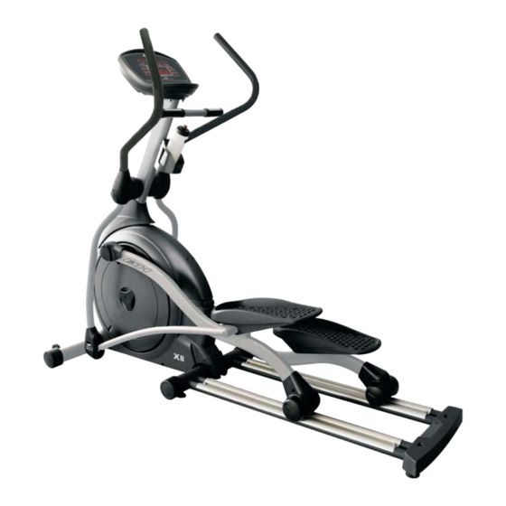
X8R Elliptical
OWNER'S MANUAL
ASSEMBLY OPERATION
MAINTENANCE
WARRANTY
PARTS ORDERING
CAUTION:
Exercise of a strenuous nature, as is customarily done on this equipment, should not be
undertaken without first consulting a physician. No specific health claims are made or implied as they
relate to the equipment.
IMPORTANT:
Read all instructions carefully before using this product. Retain this owner's
manual for future reference.
BH North America
Foothill Ranch , California 92610
Advertisement
Table of Contents

Related Manuals for BH FITNESS X8R Elliptical


Summary of Contents for BH FITNESS X8R Elliptical
- Page 1 X8R Elliptical OWNER’S MANUAL ASSEMBLY OPERATION MAINTENANCE WARRANTY PARTS ORDERING CAUTION: Exercise of a strenuous nature, as is customarily done on this equipment, should not be undertaken without first consulting a physician. No specific health claims are made or implied as they relate to the equipment.
-
Page 2: Table Of Contents
TABLE OF CONTENTS Safety………………......…..1 Training Guidelines......…..2 Parts & Hardware Contents………....6 Pre-Assembly Instructions……......9 Assembly Instructions…………………..10 Installation…………………….......21 Console Operations……………....22 Maintenance…………………………....28 Exploded View ………........29 Parts List …………………......30 Warranty……..………………………....32... -
Page 3: Safety
IMPORTANT SAFETY ADVICE PRECAUTIONS This elliptical has been designed and constructed to provide maximum safety. Nevertheless, certain precautions should be taken when using exercise equipment. Read the whole manual before assembling and using the elliptical. The following safety precautions should also be observed: 1. -
Page 4: Training Guidelines
TRAINING GUIDELINES Exercise is one of the most important factors in the overall health of an individual. Listed among its benefits are: Increased capacity for physical work (strength endurance) Increased cardiovascular (heart and arteries/veins) and respiratory efficiency Decreased risk of coronary heart disease Changes in body metabolism, e.g. - Page 5 TRAINING GUIDELINES (cont’d) Specifics Different forms of exercise produce different results. The type of exercise that is carried out is specific both to the muscle groups being used and to the energy source involved. There is little transfer of the effects of exercise, i.e. from strength training to cardiovascular fitness. That is why it is important to have an exercise program tailored to your specific needs.
- Page 6 TRAINING GUIDELINES (cont’d) The target is not a magic number, but a general guide. If you’re above average fitness, you may work quite comfortably a little above that suggested for your age group. The following table is a guide to those who are keeping fit. Here we are working at about 80% of maximum.
- Page 7 TRAINING GUIDELINES (cont’d) SUGGESTED STRETCHES The correct form for several basic stretches is shown at the right. Move slowly as you stretch—never bounce. 1. Toe Touch Stretch Stand with your knees bent slightly and slowly bend forward from your hips. Allow your back and shoulders to relax as you reach down toward your toes as far as possible.
-
Page 8: Parts & Hardware Contents
PART & HARDWARE CONTENTS... - Page 9 PART & HARDWARE CONTENTS...
- Page 10 Hardware Package Contents STEP Item Description STEP Item Description Long Hex Nut 21 Nylon Nut M12 CKS Hex Screw M10x40 Blue Loctite 22 Carriage Screw M8x45 Spring Washer M10 23 Nylon Nut M8 Flat Washer Ø10x Ø20x1.5t 24 Truss Philips Self Tapping Screw Ø5x15 Truss Philips Screw M5x10 25 Truss Philips Screw M4x15 26 Truss Philips Screw M5x10 Blue Loctite...
-
Page 11: Pre-Assembly Instructions
PRE-ASSEMBLY INSTRUCTION GENERAL INSTRUCTIONS Carefully read through the instructions contained in this manual. It provides you with important information about assembly, safety and use of the machine. 1. This unit has been designed for light commercial use. The weight of the user must not exceed 400 lbs. - Page 12 ASSEMBLY If you are missing parts or require information on how to operate this product please call (949) 206-0330.
-
Page 13: Assembly Instructions
ASSEMBLY INSTRUCTIONS Note: Assembly of this unit should take two people about 45 minutes to properly assemble. STEP 1. Assembly of Frame and Front Stabilizer 1.1 If required, rest the frame on foam or cardboard to assist during assembly. 1.2 Align the bolts on the Front Stabilizer with the holes on the front of the frame. - Page 14 ASSEMBLY INSTRUCTIONS (cont’d) STEP 3. Assemble middle cover and stabilizer 1. Place the middle cover (I) between the stabilizer assembly and tighten with screw (5). 2. Place the rear stabilizer cover (J) and tighten with washer (39) and screw (6). Attention: 1.
- Page 15 ASSEMBLY INSTRUCTIONS (cont’d) STEP 4. Assemble Pedal and Frame 1.1 Slide the wave washer (9), left pedal assembly (D-L) and flat washer (8) onto the bushing of the flywheel assembly. Secure the arrangement using the screw (7) provided. 1.2 Apply the procedures in Step 4-1.1 to the right pedal assembly. Attention: Make sure the pedal metal tube and the crank bushing are securely tightened to avoid risk of injury...
- Page 16 ASSEMBLY INSTRUCTIONS (cont’d) STEP 5. Assemble Upper Control Tube and Frame 1.1 Insert the upper control tube (E) through the plastic boot (K) and o nto the main frame’s mounting sleeve. Mate and c onnect the control cables. Secure the attached members using the screws and nuts provided (10,11,12,13). and slide the plastic boot (K) down the tube to cover the joint.
- Page 17 ASSEMBLY INSTRUCTIONS (cont’d) STEP 6. Assemble Upper Control Tube and Computer Console 1.1 Attached the computer (F) to the frame with nuts & washers (15,16). While assembling, make sure it is attached securely to avoid damages to the computer. 1.2 After attaching the computer, connect all the signal cables together. Pay attention to the alignment. Do not force the insertion if they can not be aligned.
- Page 18 ASSEMBLY INSTRUCTIONS (cont’d) STEP 7. 1.1 Secure the Handrail Tube Assembly (G-L) by sliding a Flat Washer (38) first, then 2 Wave Washers (19) over the upper control tube post and hold together with the Flat Washer (18) and screw (17) provided.
- Page 19 ASSEMBLY INSTRUCTIONS (cont’d) STEP 8. Assemble Handle and Upper Handle Tube 1.1 Insert the upper handle (H) into the upper handrail tube assembly and tighten with the nuts and bolts (22, 23) provided.
- Page 20 ASSEMBLY INSTRUCTIONS (cont’d) STEP 9. Assemble Handle plastic 1.1 Put on the handle tube cover (L) and tighten with screw (24). Attention: While tightening plastic cover, make sure they snap on and fit snugly together. STEP 10. Assemble Handle Tube and Pedal plastic 1.1 Attach the Left pedal cover (N) to the Left pedal tube.
- Page 21 ASSEMBLY INSTRUCTIONS (cont’d) STEP 11. Assemble Footplate Attach the Right Footplate (O) with the screws (26) and washers (27) provided 1.2 Repeat step 1.1 for the Left side.
- Page 22 ASSEMBLY INSTRUCTIONS (cont’d) STEP 12. Assemble Bottle Holder 1.1 Assemble the bottle holder (P) and the bottle holder mount (Q) on the upper portion of the control tube using washer (29) and screw (28).
-
Page 23: Installation
INSTALLATION IMPORTANT SAFETY INFORMATION THIS UNIT IS INTENDED FOR HOUSEHOLD USE READ ALL INSTRUCTIONS BEFORE USING THIS ELLIPTICAL CAUTION: Before starting any exercise program, it is recommended that you consult your physician. Fitness equipment must always be installed and used on a flat surface. Do not use outdoors or near water. -
Page 24: Console Operations
Console Operation Instructions MAIN DESCRIPTION The LED display console features functions such as TIME, DISTANCE, RPM, HEARTRATE, WORK LEVEL, WATT, METS, CALORIES, and PROGRAM profile. DISPLAY & POWER As the pedals move, the console will display all LED elements for 2 seconds. Dot matrix will display the lowest resistance level, the window will display SET WEIGHT 150lbs and PRESS ENTER. - Page 25 Console Operation Instructions (cont’d) III. BUTTON FUNCTIONS Pressing any button will accompany with an audible beep. Quick Start Press Quick Start button to enter Manual Mode directly and the console starts accumulating values. Time counts up, the profile cursor shifts to next column every one minute.
- Page 26 Console Operation Instructions (cont’d) PROGRAM FUNCTIONS Manual Mode Press Manual or + / – buttons to navigate to Manual Mode, the console displays the lowest level and the indicator of Manual Mode lit up. The console will display alternately. starts. SELECT WORKOUT PRESS ENTER SETTING MODE...
- Page 27 Console Operation Instructions (cont’d) Program Mode Select Random, Weight Loss, CV Workout, Hill Intervals by pressing the corresponding button or by pressing + / - buttons. Dot matrix displays profiles and the indicators of the program selected. The screen will display and PRESS ENTER SELECT WORKOUT alternately then Program Mode...
- Page 28 Console Operation Instructions (cont’d) 2. Press ENTER at this time, LED screen will flash. Now users can press adjust their age (range:10 - 99 years - preset value is 25, step is 1). Based on the input value, the target pulse will be calculated. Press’ ’to confirm 3.
- Page 29 Console Operation Instructions (cont’d) PROFILES Manual Mode Random Profile (Display at random) Weight Loss Profile Hill Intervals Profile CV Workout Profile HRC Profile...
-
Page 30: Maintenance
MAINTENANCE INSTRUCTIONS CLEANING WARNING: Always unplug your elliptical prior to cleaning or servicing your unit, in order to avoid electrical hazard or shock. has been taken to assure that your elliptical has been properly adjusted and Care lubricated at the factory. It is not recommended that the user attempt service on the internal components instead seek service from an authorized service center. -
Page 32: Parts List
PARTS LIST Part No. Part No. Description Description (A) Main Frame and Frame Assembly Fittings (D) Turn Plate Cross Assembly and Attachments A01 JEA2-A1001 Frame Assembly D01 JEA1-G1001 T urn Plate Cross Assembly A02 JEA1-C1001 Grank Set Assembly D02 P-1504 Plastic T urn Plate A03 JEA1-D1002 Idler Wheel Assembly... - Page 33 Part No. Part No. Description Description C08 SCI5-12 Truss Philips Self Tapping Screw Φ5x12 K03 P-2565 Right Stabilizer Tube Cover (G) pper Control Tube Set K04 P-2559 Left Front Handrail Cover G01 JED5-P1001 Upper Frame Assembly K05 P-2558 Left Rear Handrail Cover G02 SGA10-70I CKS Hex Screw M10xP1.5x70 K06 P-2561...
-
Page 34: Warranty
For more detailed warranty information or to register your product warranty easily online, visit our website at: www.BHFitnessUSA.com FOR WARRANTY REPAIRS, PLEASE DO NOT TAKE YOUR MACHINE BACK TO THE RETAIL STORE. CONTACT BH FITNESS FIRST. BH North America Corporation 20155 Ellipse Foothill Ranch, CA 92610 Phone: 949.206.0330;...
Need help?
Do you have a question about the X8R Elliptical and is the answer not in the manual?
Questions and answers