Table of Contents
Advertisement
Quick Links
Advertisement
Table of Contents

Subscribe to Our Youtube Channel
Related Manuals for Avery Dennison ALS 104


Summary of Contents for Avery Dennison ALS 104
- Page 1 ANUAL Label Dispenser Edition 5 4/2010...
-
Page 3: Table Of Contents
ONTENTS Please note Label sensor ......17 Power supply ......17 Electronics . - Page 4 ONTENTS After operation 2.4.3 Threading the label web ....30 Threading guide ......30 Threading the label roll at the dispensing edge.
-
Page 5: Please Note
Validity and binding effect of this manual 1.1.1 Contents Copyright This technical manual refers exclusively to the ALS 104 Avery Dennison holds all rights to this manual and its Label Dispenser. It is written for the purpose of appendices. Reproduction, reprinting or any other ensuring professional usage and calibration of the unit. -
Page 6: Illustrations And Descriptions
A capital letter after a figure number, for example [12A], refers to a specific section of the figure. Sentences starting with an arrow are instructions and Generally, the label dispenser shown is an ALS 104 guidelines. right-handed version. The left-handed version is only... -
Page 7: Safety Instructions
LEASE NOTE 1.2 S AFETY INSTRUCTIONS SAFETY INSTRUCTIONS Information and qualifications Ensure the required qualifications are met 1.2.1 Ensure that only trained and authorized personnel Follow the instructions operate, configure and service the unit. WARNING! Only allow qualified and well-trained expert personnel or service technicians to perform Safe and efficient operation of the label configurations. -
Page 8: Operational Safety Of The Unit
1.2.2 Proper usage WARNING The unit is not protected against splashing The ALS 104 Label Dispenser is a fully automatic unit water in its standard model. for attaching self-adhesive labels to products or Keep the unit dry. packaging. The company operating the unit must install... -
Page 9: Protection Against Injuries By Mechanical Action
LEASE NOTE 1.2 S AFETY INSTRUCTIONS Protection against injuries by mechanical action WARNING! Risk of injury due to moving and rapidly rotating parts! – Long hair, loose jewellery, long sleeves, and so on are not permissible when using the unit. Sufficient protective clothing must be worn. -
Page 10: Before Beginning Production
LEASE NOTE 1.2 S AFETY INSTRUCTIONS Before beginning production 1.2.3 Due diligence of the operating company Due diligence of the user and the service technician Check that the safety installations are working properly. Ensure that the following prerequisites are fulfilled in Inspect the machinery for any visible damage. -
Page 11: Safety Notes On The Unit
Keep hands clear of rollers. A5346 [1] Left: ‘Pinch Point’ warning. Right: Position of the warning note on the ALS 104. Item number of the label: A5346. The blue label ‘Read manual’ [2] demands that users read the unit instructions. -
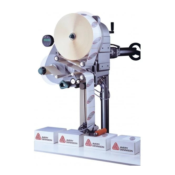
Page 12: Product Description
RODUCT DESCRIPTION 2.1 O VERVIEW RO D U CT D ES CR IP TI ON OVERVIEW Components 2.1.1 [3] ALS 104 Label Dispenser (right-handed version) - Page 13 RODUCT DESCRIPTION 2.1 O VERVIEW A Control panel Dispensing edge – For sending commands to the device and for – Standard: (non-adjustable) L-shaped dispensing displaying operating states and error messages. edge – An optional external control panel can also be –...
-
Page 14: Control Panel
12.2 fix Status LED – – Explanation Dispensing mode Configuration mode [4] Control panel of the ALS 104 A Operating LED Flashing Error B Status LED C LCD display [5] Meaning of the red status LED D Buttons LCD display –... -
Page 15: Connection Arrangement
Connections on the back of the device Sensor connections [6] Connections on the back of the ALS 104: [7] Position of the sensor connections on the ALS 104 A Power supply connection B Signal interface (Sub-D15 port) C RS232 interface (Sub-D9 port) D Connection for external control panel (PS/2 port) [8] Arrangement of the sensor connections (schematic) on the LH (left figure) and RH (right figure) devices. -
Page 16: Mode Of Operation
An electronic signal is output at the same time. The signal can be fed to an external cont- roller and evaluated. [9] The ALS 104 is ready for operation in its idle mode. A Dancer arm B Pressure roller... -
Page 17: Technical Specifications
RODUCT DESCRIPTION 2.1 O VERVIEW Technical specifications Power supply 2.1.5 System voltage: 115 V (AC) at 60 Hz po- wer frequency Characteristics 230 V (AC) at 50 Hz po- wer frequency Dispensing speed: up to 30 m/min Power consumption: 300 VA Labelling halt precision ±... -
Page 18: Internal Interfaces
RODUCT DESCRIPTION 2.1 O VERVIEW PLC outputs: 3x PNP, 24 V, max. Protection class: IP 21 (connection with D-Sub 500 mA/channel, total IP 65 optional (with ex- 15 connector, optional permissible output cur- tras) with 8-pin M12) rent: 1500 mA One insulated relay out- Integration put, max. -
Page 19: Design Models
2.1 O VERVIEW Design models 2.1.6 The ALS 104 Label Dispenser is available in two de- signs for differing conveyor belt directions. Right-handed version – The products are transported from left to right [10]. – The dispensing edge is located on the right side. -
Page 20: Options
RODUCT DESCRIPTION 2.2 O PTIONS OPTIONS External control panel – An external control panel can be connected in addition to the integrated control panel. – An external control panel is useful if the standard control panel is inaccessible due to the position in which the unit is installed. -
Page 21: Pneumatic Dispensing Edge
RODUCT DESCRIPTION 2.2 O PTIONS Pneumatic dispensing edge – The dispensing edge is pivoted in the dispensing head. Compressed air presses the dispensing edge onto the surface of the product. – Allows compensation for height differences between the products or on the product surface. [16] Pneumatic dispensing edge V-shape dispensing edge –... -
Page 22: Outer Diameter Control Sensor
RODUCT DESCRIPTION 2.2 O PTIONS Outer Diameter control sensor The outer diameter control sensor (OD sensor) triggers a warning, if the label roll outer diameter falls below a certain, adjustable value. [19] OD sensor (pictured red resp. dark gray) Dust/Splash guard Available only for ALS 20X. -
Page 23: Printer
2.2 O PTIONS Printer – If necessary, you can mount a hot stamp printer (not available from Avery Dennison) onto the holder brackets of the dispensing edge. – Example of use: Printing consecutive numbers onto labels. Narrow label spring kit... -
Page 24: Operating Modes
RODUCT DESCRIPTION 2.3 O PERATING MODES OPERATING MODES Dispensing mode 2.3.1 – This is the operating mode of the unit when switched – The display shows the dispensing speed [22A] and the start offset [22C]. STATUS – In dispensing mode, the button assignments are as shown on the buttons. -
Page 25: Configuration Mode
RODUCT DESCRIPTION 2.3 O PERATING MODES Configuration mode 2.3.2 Switching to configuration mode: Press the buttons STATUS – Display: LABEL SETUP Speed Offset 12.2 fix – LABEL SETUP is the name of the first menu shown – – directly after switching to configuration mode. –... -
Page 26: Functions
RODUCT DESCRIPTION 2.3 O PERATING MODES Functions Every submenu contains functions for setting the unit controls. Figure [24] shows the buttons functions for changing LABEL SETUP > LABEL SETUP the configuration with the example of Missing Labels. LABEL SETUP Label Size LABEL SETUP Missing Labels Missing Labels... -
Page 27: Function Descriptions
Function Missing Labels: – Missing labels Function Machine Type – In practice, sometimes labels are missing from the – ALS 104 LH: Left-handed unit backing paper. The fault tolerance is defined using – ALS 104 RH: Right-handed unit the Missing Labels function. -
Page 28: Inserting Label Material
Ensure that only authorised persons are within the operating range of the machine. [26] Main switch (A) on the housing. Use the required personal protective equipment correctly; forexample, wear a hairnet, safety glasses. [27] Main switch on ALS 104 with dust/splash guard option. -
Page 29: Inserting A Label Roll
EFORE OPERATION 2.4 I NSERTING LABEL MATERIAL Inserting a label roll 2.4.2 WARNING! Risk of injury due to moving and rapidly rotating parts! Before inserting the label roll, ensure that the device is turned off at the main switch. Do not under any circumstances turn the device on before the label strip is threaded in completely. -
Page 30: Threading The Label Web
2.4 I NSERTING LABEL MATERIAL Threading the label web 2.4.3 Threading guide [30] Threading guide for ALS 104 with L-shape dispensing edge A Right-handed version B Left-handed version [31] Threading guide for ALS 104 with V-shape dispensing edge A Right-handed version B Left-handed version *) Solid line: Path for label rolls with labels facing outwards. -
Page 31: Threading The Label Roll At The Dispensing Edge
EFORE OPERATION 2.4 I NSERTING LABEL MATERIAL Threading the label roll at the dispensing edge Unroll around 1 m of label strip and remove the labels from it. Pass the backing paper around the first deflection roller [32A] and through the slot in the sensor [32B]. Feed the backing paper under the pressure roller [32C] to the dispensing plate [32D]. -
Page 32: Threading The Label Roll Onto The Drive Roller
EFORE OPERATION 2.4 I NSERTING LABEL MATERIAL Threading the label roll onto the drive roller Open the pressure roller. To do so, rotate the lever [35D] in a clockwise direction. Feed the backing paper around the deflection roller [35B], drive roller [35C] and the tensioning plate [35A]. -
Page 33: Electrical Connections
Checking the power supply setting The ALS 104 is suitable for operation with a power supply of 230 V (AC) or 115 V (AC). If you are unsure of what mains voltage your lo- cal electricity supplier provides, refer to a qual- ified service technician. -
Page 34: Connecting The Power Cable
LECTRICAL CONNECTIONS Connecting the power cable. Ensure that power switch [39A] is set to “O” (off). Using the supplied power cable, plug the ALS 104 into a socket connected to the mains supply. [39] Power cable (B) plugged in. Power supply with dust/splash 3.1.2... -
Page 35: Mechanical Settings
EFORE OPERATION 3.2 M ECHANICAL SETTINGS MECHANICAL SETTINGS Adjusting the unwinder’s core 3.2.1 diameter Tool: – 3 mm hexagon (Allen) screwdriver The unwinder can be adjusted with core adapters [41B] to fit the inner diameter of the label roll. The adapters must be fitted and dismantled in different ways depending on this diameter: –... -
Page 36: Calibrating The Label Sensor
EFORE OPERATION 3.2 M ECHANICAL SETTINGS Calibrating the label sensor 3.2.3 Positioning the sensor: Release the thumb screw. Position the sensor along the axle in such a way as to allow it to register the spaces between the labels. Configuring the sensor: –... -
Page 37: Start-Up And Shutdown
– The main switch [47A] lights, if the machine is swit- ched on. Operate the main switch. – Once on, the ALS 104 is in dispensing mode; in other words, triggering the product sensor will cause a label to be dispensed. -
Page 38: Configuration And Monitoring
The next label to be dispensed is halted in the label stop position. This is useful if the label protrudes over the dispensing edge somewhat [48]. ALS 104 is pre-configured for use with the supplied label sensor. If this sensor is employed, the label stop position setting will only require minimal correction. -
Page 39: Dispensing Speed
PERATION 4.2 C ONFIGURATION AND MONITORING Dispensing speed The dispensing speed can be set to a fixed value or can be configured to automatically adjust to the speed of the conveyor belt (speed adaption). The second possibility requires a speed sensor to be connected; it measures and relays the conveyor speed to the dispenser. -
Page 40: Label Position On The Product
PERATION 4.2 C ONFIGURATION AND MONITORING Label position on the product Prerequisites: – The label length must be specified. – The label stop position must be set. The Start Offset is set in dispensing mode with the right two keys (see “Dispensing mode” on page 24). –... -
Page 41: Monitoring Functions
PERATION 4.2 C ONFIGURATION AND MONITORING Monitoring functions 4.2.2 While in dispensing mode, an electronic control monitors the following functions: Missing labels A label missing from the label roll does not normally affect the dispensing operation, because the label feed continues until a label’s edge passes under the label sensor. -
Page 42: After Operation
Only replace fuses with the type and [51] Unlock the fuse insert. rating specified in this manual. ALS 104 with dust/splash guard: Fuses may only be replaced by qualified service techni- cians. Turn off the unit. Unplug the power cable. -
Page 43: Cleaning Agents
FTER OPERATION 5.1 M AINTENANCE AND CLEANING Cleaning agents Regular maintenance 5.1.2 5.1.3 Cleaning agents for rubber rollers: The label dispenser is designed to be mainte- – Roller cleaner, order number 98925. nance-free. However, you should service the unit regu- If other cleaning agents are used, there is a larly in order to ensure reliable long-term operating chance the rubber may corrode. -
Page 44: Operational Failures
PERATIONAL FAILURES 6.1 E RROR MESSAGES PE RA TI O NA L FA ILU R ES ERROR MESSAGES Error messaging 6.1.1 Error messages are displayed as follows: xxxxxxxxxxxxxxxx Reset Alarm? xxxxxxxxxxxxxxxx = Message text At the same time, a signal is activated at the signal output of the unit, which can be used to switch on an external visual or audible signal. -
Page 45: Avery Dennison Deutschland Gmbh Ohmstrasse
7.1 EC DECLARATION OF CONFORMITY P PE ND IX EC DECLARATION OF CONFORMITY Avery Dennison Deutschland GmbH Ohmstrasse 3 85386 Eching, Germany herewith assert that we have designed and built the device described in the following to conform with the basic safety and health requirements of the relevant EU directives. - Page 47 Avery Dennison Deutschland GmbH Ohmstraße 3 85386 Eching Germany Telephone: +49-8165-925-0 http://www.machines.averydennison.com...
Need help?
Do you have a question about the ALS 104 and is the answer not in the manual?
Questions and answers