Patton electronics 2616RC Getting Started Manual
T1/e1 tdm-digital access concentrator (t-dac)
Hide thumbs
Also See for 2616RC:
- Specifications (2 pages) ,
- User manual (80 pages) ,
- Administrator's reference manual (315 pages)
Table of Contents
Advertisement
Quick Links
Download this manual
See also:
User Manual
See Chapter 2 for installa-
tion procedures & Chapter 3
for configuration procedures
Model 2616RC
T1/E1 TDM-Digital Access
Concentrator (T-DAC)
Getting Started Guide
Important
This is a Class A device and is intended for use in a light industrial environment. It is not intended nor approved for use in an industrial
or residential environment.
Sales Office:
+1 (301) 975-1000
Technical Support:
+1 (301) 975-1007
E-mail:
support@patton.com
WWW:
www.patton.com
Document Number: 11015U1-001 Rev. D
Part Number: 07MD2616RC-GSG
Revised: April 9, 2009
Advertisement
Table of Contents

Related Manuals for Patton electronics 2616RC


Summary of Contents for Patton electronics 2616RC
- Page 1 See Chapter 2 for installa- tion procedures & Chapter 3 for configuration procedures Model 2616RC T1/E1 TDM-Digital Access Concentrator (T-DAC) Getting Started Guide Important This is a Class A device and is intended for use in a light industrial environment. It is not intended nor approved for use in an industrial or residential environment.
- Page 2 The software described in this document is furnished under a license and may be used or copied only in accordance with the terms of such license. Patton Electronics warrants all Model 2616RC components to be free from defects, and will—at our option—repair or replace the product should it fail within one year from the first date of the shipment.
- Page 3 Summary Table of Contents Introduction ..............................13 Hardware installation............................ 19 Configuring the T-DAC for operation ......................31 Operation and shutdown ..........................58 Troubleshooting and maintenance ........................ 60 Contacting Patton for assistance ........................72 Compliance information ..........................75 68-pin SCSI-to-open-end 6-foot cable (part #10-3096TM68-6) ..............
-
Page 4: Table Of Contents
Precautions ................................11 Typographical conventions used in this document....................12 General conventions ............................12 Mouse conventions ............................12 Introduction ..............................13 Model 2616RC T1/E1 T-DAC overview ......................14 Hardware overview ..............................15 ................................15 ................................15 RS-232 control port ............................16 Power system ..............................16 Central processing unit ...........................16... - Page 5 Connecting the DB9-RJ45 adapter with the included cable ................33 Setting up the HyperTerminal (or similar program) session ................34 Using a browser to complete Model 2616RC configuration ..................37 Displaying the T-DAC 2616RC web administration pages ................38 Home page overview ..........................38 Configuring the default gateway ........................40...
- Page 6 Model 2616RC T-DAC Getting Started Guide Contents Warranty Service and Returned Merchandise Authorizations (RMAs)..............73 Warranty coverage ............................73 Out-of-warranty service ..........................73 Returns for credit ............................73 Return for credit policy ..........................74 RMA numbers ..............................74 Shipping instructions ..........................74 Compliance information ..........................75 Compliance ................................76...
- Page 7 Model 2616RC network and configuration ports ........
- Page 8 2616RC Configuration Menu home page ........
- Page 9 List of Tables General conventions ..............12 Mouse conventions .
-
Page 10: About This Guide
About this guide This guide describes installing and configuring a Patton Electronics Model 2616RC TDM-Digital Access Con- centrator (T-DAC). By the time you are finished with this guide, your T-DAC will be connected to T1/E1 lines and transferring data. The instructions in this guide are based on the following assumptions: •... -
Page 11: Precautions
Strictly follow the instructions to avoid property damage. CAUTION Safety when working with electricity • The Model 2616RC shall be installed in a restricted access location accessi- ble only to authorized personnel. WARNING • This unit contains no user-serviceable parts. Refer servicing to qualified personnel. -
Page 12: Typographical Conventions Used In This Document
Model 2616RC T-DAC Getting Started Guide About this guide Typographical conventions used in this document This section describes the typographical conventions and terms used in this guide. General conventions The procedures described in this manual use the following text conventions: Table 1. -
Page 13: Introduction
Chapter 1 Introduction Chapter contents Model 2616RC T1/E1 T-DAC overview ......................14 Hardware overview ..............................15 ................................15 ................................15 RS-232 control port ............................16 Power system ..............................16 Central processing unit ...........................16 System timing ..............................16 Temperature ..............................16 Altitude ................................16 Humidity ................................16 Physical dimensions ............................16 Management services ............................16... -
Page 14: Model 2616Rc T1/E1 T-Dac Overview
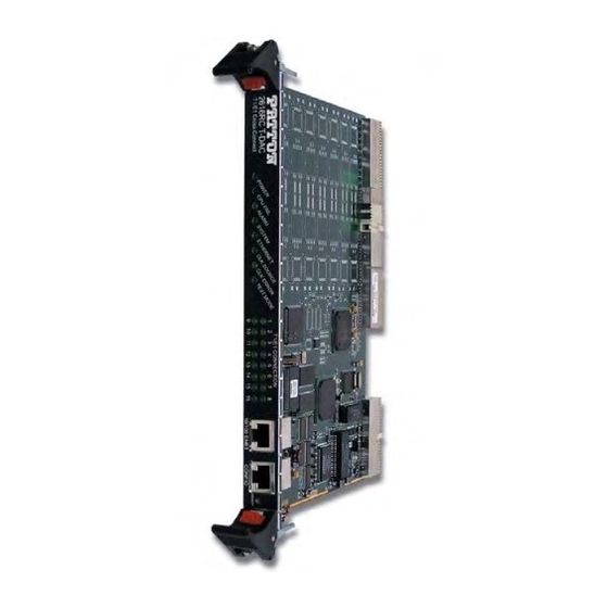
Model 2616RC T-DAC Getting Started Guide 1 • Introduction Model 2616RC T1/E1 T-DAC overview The Model 2616RC (see figure 1) provides 16 T1/E1 ports. A built-in digital cross-connect switch provides completely flexible grooming: the capability to connect any DS0-channel to any other DS0-channel from the WAN uplink ports or the T1/E1 ports. -
Page 15: Hardware Overview
Figure 2. Model 2616RC T-DAC features The 2616RC includes 4, 8, 12, or 16 ports selectable for T1 or E1 operation. The T1/E1 ports may be con- nected to ATM/FR/DDN/IP network backbones and are accessible via the 68-pin SCSI connector in the rear of the unit. -
Page 16: Rs-232 Control Port
Hardware flow control (RTS and CTS) Power system The 2616RC obtains power from the Patton ForeFront chassis. Total power consumption is a maximum of 43 watts provided by modular power supplies installed in the Patton ForeFront chassis. Central processing unit The 2616RC employs an Intel i960VH RISC processor operating at 100 MHz/100 Mips. -
Page 17: Model 2616Rc Front Panel Leds
SYSLOG Client • Remote Software Upgrade via FTP • Built-in HTTP server for complete configuration and control using a standard web browser • Frame Relay or PPP in-band management via T1/E1 DS0s. Figure 3. Model 2616RC front panel LEDs Hardware overview... -
Page 18: Led Display
The 2616RC is set as the slave, getting its clock from the H.110 Bus. CLK ERROR Yellow On solid Master Clock source has been lost and the 2616RC is using the secondary source for its clock. Flashing Master Clock source and the Secondary Clock source have been lost and the 2616RC is using its internal crystal for its clock. -
Page 19: Hardware Installation
Chapter 2 Hardware installation Chapter contents Introduction ................................20 Unpacking the Model 2616RC T-DAC ........................20 T-DAC blades installation .............................20 Cable installation..............................22 Connecting the Ethernet ports ........................22 Connecting the 10/100Base-T Ethernet port to an Ethernet switch or hub ..........22 Connecting the 10/100Base-T Ethernet port to an Ethernet-capable workstation or PC .........23... -
Page 20: Introduction
A DB9-RJ45 (EIA-561) adapter for connecting a PC's serial port to the T-DAC console port • Model 2616RC T-DAC Getting Started Guide • CD-ROM containing product literature, the Model 2616RC T1/E1 T-DAC Getting Started Guide, and the Model 2616RC, 3096RC, and 3196RC Administrator's Reference Guide T-DAC blades installation Do the following:... -
Page 21: Alignment/Esd Pin And Card Handle
Model 2616RC T-DAC Getting Started Guide 2 • Hardware installation Note The T-DAC should be installed as close as possible to the termination jack provided by the Telco. The location should be well ventilated. Do not block the rack chassis’ cooling vents. -
Page 22: Cable Installation
LAN and automatically negotiate half or full-duplex operation. This sec- tion describes connecting the T-DAC to the Ethernet LAN via an Ethernet hub, switch, or workstation. Figure 5. Model 2616RC network and configuration ports Connecting the 10/100Base-T Ethernet port to an Ethernet switch or hub The 10/100Base-T Ethernet port (see figure 5) is designed to connect to an Ethernet switch or hub. -
Page 23: Connecting The 10/100Base-T Ethernet Port To An Ethernet-Capable Workstation Or Pc
Model 2616RC T-DAC Getting Started Guide 2 • Hardware installation Figure 6. Ethernet RJ-45 pin and signal definitions for T-DAC Connecting the 10/100Base-T Ethernet port to an Ethernet-capable workstation or PC The 10/100Base-T Ethernet port can connect to a single Ethernet-capable workstation or PC by means of a cross over cable. -
Page 24: Connecting The T1/E1 Wan Ports
Connecting the T1/E1 WAN ports An active T1/E1 is not necessary to configure the T-DAC. However, active T1/E1 connections are required when mapping WAN time slots to other WAN time slots. The factory-set default configuration of the Model 2616RC has the T1/E1 ports disabled. -
Page 25: Wan Cable's 68-Pin Scsi Connector
10) of the 6-foot WAN cable (see figure 9 on page 24) to the connector on the rear panel of the Model 2616RC. 2. Connect the WAN cable RJ-45 connectors (see figure 11) to the corresponding ports on a patch panel or local T1/E1 device. -
Page 26: 68-Pin Scsi To Open End Cable
68-pin SCSI to open end cable The SCSI-to-open-end cable (see figure 12) connects the 2616RC T1/E1 lines to a punch-down block via 24 gauge solid wire (0.5mm). The other end will be unterminated, open-end twisted pairs. Refer to table 5 punch-down block wiring information. -
Page 27: Wan Cable's 68 Non-Terminated Twisted-Pairs
Model 2616RC T-DAC Getting Started Guide 2 • Hardware installation Note The 64 wires in this cable are grouped into blue and orange binders of 32 wires each. Wires in the blue binder have the same color scheme as wires in the orange binder, so it is important to keep each binder sepa- rated to avoid confusion when connecting to a punch-down block. -
Page 28: Installing The Wan Cable To A Punch-Down Block
Model 2616RC T-DAC Getting Started Guide 2 • Hardware installation Table 5. WAN cable’s 68 non-terminated twisted-pairs (Continued) Port/Directio 68 Pin Wire Color Port/Directio 68 Pin Wire Color Pairs Pairs Positions Code Positions Code — NOT USED — NOT USED... -
Page 29: 68-Pin Scsi To Open End, 6 Foot Cable (Part #10-3096Tm68-6)-Obsolete
68-pin SCSI to 64-pin female Telco (part #10-3096TM68/64-6) Do the following to install the 6-foot cable adapter for connection of the 2616RC to a Patton E1 balun rack Models 464RC and 466RC. 1. Connect the 68-pin SCSI connector of the WAN cable to the connector on the rear panel of the Model 2616RC. -
Page 30: Completing The Hardware Installation
Power is delivered from the Patton ForeFront chassis backplane through the 47-pin PICMG 2.11 power con- nectors on the 2616RC blades. Upon insertion into the Patton ForeFront chassis, the Model 2616RC immedi- ately powers up and begins its boot cycle. During the boot cycle the following should occur: 1. -
Page 31: Configuring The T-Dac For Operation
Connecting the DB9-RJ45 adapter with the included cable ................33 Setting up the HyperTerminal (or similar program) session ................34 Using a browser to complete Model 2616RC configuration ..................37 Displaying the T-DAC 2616RC web administration pages ................38 Home page overview ..........................38 Configuring the default gateway ........................40... -
Page 32: Introduction
Model 2616RC T-DAC Getting Started Guide 3 • Configuring the T-DAC for operation Introduction This chapter contains the following procedures that describe configuring the Model 2616RC T-DAC for operation: • “Configuration prerequisites”—lists the items you need to have on hand before configuring the T-DAC. -
Page 33: Initial Configuration Through The Rs-232 Control Port
Connecting the DB9-RJ45 adapter with the included cable Do the following: 1. Find the DB9-RJ45 adapter for your PC and RJ-45-to-RJ45 cable shipped with your 2616RC T-DAC. 2. Connect the DB9-RJ45 adapter to your PC’s RS-232 serial port. 3. Connect the RJ45-RJ45 cable between the adapter which you installed in step 1 and the RS-232 Config port on the front of the Model 2616RC (figure... -
Page 34: Setting Up The Hyperterminal (Or Similar Program) Session
1. At your PC, find the file HYPERTRM.EXE. Open a HyperTerminal session by double-clicking on the file name. Figure 17. Connection Description window 2. Type a connection name (e.g., 2616RC Config), select an icon, then click (figure 18). Figure 18. Connect To window 3. -
Page 35: Com1 Properties Window
Model 2616RC T-DAC Getting Started Guide 3 • Configuring the T-DAC for operation 6. Configure your COM port settings as shown in figure 19, then click Figure 19. COM1 Properties window 7. Click on the menu, then select Properties. File 8. -
Page 36: Login Window
Model 2616RC T-DAC Getting Started Guide 3 • Configuring the T-DAC for operation 9. Connect the male end of the 2616RC T-DAC’s power cables to the power outlets. 10. Boot up information will display on your HyperTerminal connection window, eventually followed by a login request window (see figure... -
Page 37: Using A Browser To Complete Model 2616Rc Configuration
(store Config(1)) to save the changes you have just made to the configuration. This completes the initial configuration of the Model 2616RC. The next steps in configuration will be done using your Web browser connected via Ethernet to the 2616RC. -
Page 38: Displaying The T-Dac 2616Rc Web Administration Pages
2. Connect the 2616RC’s T-DAC 10/100 Ethernet connection to the Ethernet LAN. 3. At your PC, open a Web browser session. In your browser’s URL/address field type the IP address of the Model 2616RC (for example, if the Model 2616RC’s IP address 123.124.221.10, you would type 123.124.221.10 in the browser’s URL/address field). -
Page 39: Home Page Window Panes
DRAM memory to FLASH memory. Once the configuration is saved into FLASH memory, the configuration will not be lost even if the power is cycled on the 2616RC. Initially, changes made to the 2616RC configuration are stored in volatile DRAM, enabling the user to set the box up with a working configuration before committing it to storage in FLASH. -
Page 40: Configuring The Default Gateway
27). Figure 27. IP Routing Information Page 3. The existing route you see in the table is the LAN IP address you assigned to the 2616RC during initial configuration through the RS-232 control port, earlier in this chapter. 4. To enter the default gateway, use the first . -
Page 41: Configuring The System Clocking Parameters
Example 1 Your 2616RC is the only blade in the chassis and must be configured as the system clocking master. This example assumes you will use T1/E1 port #1 as the main reference and T1/E1 port #2 as the fallback reference define the clocking source, do the following:... - Page 42 Example 2 Another card such as the Patton Model 6511 is the clocking master and your 2616RC is a secondary or slave. This example assumes you will use the system clock as the main reference and WAN port #1 as the fallback ref- erence.
-
Page 43: Clock Reference Submit Query Button
Model 2616RC T-DAC Getting Started Guide 3 • Configuring the T-DAC for operation 2. Click the System Clocking hyperlink on the 2616RC Configuration Menu to open the System Clocking Configuration page (see figure 30). Figure 30. System Clocking Configuration page, example 2 3. -
Page 44: Configuring The Ds0 Mapping
• Mapping DS0s from a T1/E1 port to an STM-1 card in the same chassis. In this scenario, the 2616RC first maps DS0s from a T1/E1 port to an H.110 port (TDM system bus). The system TDM bus, connected to all cards in the system, connects with a Patton 6511RC STM-1 card;... - Page 45 T1/E1 DS0s mapped to the H.110 (TDM bus system). – Device Number. Defines which T1/E1 port number on the 2616RC you are mapping. For example, to map a connection for T1/E1 port 3 you would select port3(3).
-
Page 46: Configuring Line Settings And Signaling For E1
Submit Query Configuring line settings and signaling for E1 Accessing the Line Interface Settings 1. On the 2616RC Configuration Menu, click the T1/E1 Link hyperlink to open the T1/E1 LINK ACTIV- ITY OVERVIEW page (see figure 35). Figure 35. T1/E1 Link Activity Overview page... -
Page 47: Configuring The E1 Line Interface Settings
37) and view the Line Interface Settings. Figure 37. WAN Circuit Configuration page, Line Interface Settings Configuring the E1 line interface settings 1. From the Line Type pull-down menu (figure 38) select dsx1E1(4) or dsx1E1-CRC(5). Using a browser to complete Model 2616RC configuration... -
Page 48: Line Type Pull-Down Menu
At this point the T1/E1 front panel LEDs will become active. The T1/E1 indicator LEDs should now display a steady green light, indicating the T-DAC has synchronized with the E1 line. If the E1 line is not connected to the 2616RC, T1/E1 link pages will display the hyperlink ALARMS PRESENT (figure 41) for that T1/E1 link. -
Page 49: Configuring Line Settings And Signaling For T1
3 • Configuring the T-DAC for operation Figure 41. E1 ALARMS PRESENT indicator After you connect the E1 line to the WAN port on the rear of the Model 2616RC these alarms should disappear. Configuring line settings and signaling for T1 Accessing the Line Interface Settings 1. -
Page 50: Configuring The T1 Line Settings
1. From the Line Type pull-down menu (figure 45) select either: – dsx1ESF(2) - indicates Extended SuperFrame DS1 – dsx1D4 - indicates AT&T D4 format DS1 Figure 45. Line Type pull-down menu with dsx1ESF(2) selected Using a browser to complete Model 2616RC configuration... -
Page 51: Line Coding Pull-Down Menu With Dsx1B8Zs(2) Selected
Figure 48. T1 ALARMS PRESENT indicator on T1/E1 LINK ACTIVITY page After you connect the E1 line to the WAN port on the rear of the Model 2616RC, these alarms should disappear. Using a browser to complete Model 2616RC configuration... -
Page 52: Enabling/Disabling The Alarm Card
49) is where you can configure the alarm card polling mode to determine whether the 2616RC monitors the alarm card status for the chassis. 1. Click on Alarm Card under the configuration menu to display the Alarm Card Information window. -
Page 53: Saving Your Configuration
At this point you have completed the basic configuration of your T-DAC for operation. To save your configu- ration settings in non-volatile RAM, do the following: 1. On the Configuration Menu click the Select HOME hyperlink to open the 2616RC Configuration Menu home page (figure... -
Page 54: Import/Export Page
Model 2616RC T-DAC Getting Started Guide 3 • Configuring the T-DAC for operation To import or export a configuration, do the following: 1. On the Configuration Menu pane, click the Import/Export hyperlink to display the IMPORT/EXPORT page (see figure 51). -
Page 55: Backing Up The Configuration Store In Flash Memory
Model 2616RC T-DAC Getting Started Guide 3 • Configuring the T-DAC for operation Backing up the configuration store in flash memory 1. To make a back-up copy of the configuration file currently stored in your T-DAC’s flash memory: – On the Import/Export page (figure... -
Page 56: Completing The Installation
2. Verify the green POWER LED is lit. If the POWER LED is flashing green, refer to Chapter 5, “Trouble- shooting and maintenance”. 3. Verify that the WAN LED illuminates, indicating that the Model 2616RC is synchronized with the T1/E1 signal. - Page 57 Congratulations! Your T-DAC is now installed. If you require further information about configuring your T- DAC settings, refer to the DSL T-DAC Administrator’s Reference Guide included on your Model 2616RC CD-ROM.
-
Page 58: Operation And Shutdown
Chapter 4 Operation and shutdown Chapter contents Introduction ................................59 Activating the Model 2616RC..........................59 De-activating the Model 2616RC..........................59... -
Page 59: Introduction
Be sure to wear an anti-static strap to prevent electrostatic damage to the blade. 1. Unlock the handles on the front of the 2616RC by pressing the red button on each handle. The button immediately activates the switch (turning it to an open position), while the button itself remains depressed. -
Page 60: Troubleshooting And Maintenance
DSX1 payload loop (dsx1PayloadLoop) ......................64 DSX1 line loop (dsxLineLoop) ........................65 Periodic maintenance ............................66 Calibration ..............................66 Maintenance................................66 Exporting the current Model 2616RC configuration ..................66 Removing the defective Model 2616RC ....................69 Installing the replacement Model 2616RC ....................70 Importing a saved configuration ........................70 Completing the installation... -
Page 61: Symptoms
POWER LED (green) is The 2616RC has detected a power failure on a power bus. There may be a problem with the Patton ForeFront chassis power system which feeds the Model 2616RC such as a failed flashing power supply module in the chassis. -
Page 62: Fault Analysis
5 • Troubleshooting and maintenance Fault analysis The following procedures outline steps you should follow when troubleshooting a Model 2616RC malfunction. 1. If possible, talk to the person who filed the trouble complaint and determine the operational symptoms. Record the symptoms on the appropriate trouble report form (include the front panel LED indications). - Page 63 The 2616RC is set as the slave, getting its clock from the H.110 Bus. No action recommended. CLK ERROR Front panel Yellow On solid Master Clock source has been lost and the 2616RC is using the secondary source for its clock. Flashing Master Clock source and the Secondary Clock source have been lost and the 2616RC is using its internal crystal for its clock.
-
Page 64: T1/E1 Port Test Modes
Do not remove card from chassis. T1/E1 port test modes The 2616RC offers a number of diagnostics tools to test operation and performance of the T1/E1 ports and line. Diagnostics include DSX1 payload loop and DSX1 line loop. DSX1 payload loop (dsx1PayloadLoop) When activated, the received signal at the selected T1/E1 port, will be looped through the 2616RC (see figure... -
Page 65: Dsx1 Line Loop (Dsxlineloop)
Model 2616RC T-DAC Getting Started Guide 5 • Troubleshooting and maintenance DSX1 line loop (dsxLineLoop) When activated, data received at the selected T1/E1 port, is looped back to the originating device (see figure 55). Data is looped at the T1/E1 port. -
Page 66: Periodic Maintenance
Calibration The Model 2616RC requires no calibration. Maintenance If you isolate a problem to the a Model 2616RC component, the entire Model 2616RC must be replaced as follows. Exporting the current Model 2616RC configuration The 2616RC T-DAC provides Import/Export functions. These functions enable you to back up (export) and restore (import) your T-DAC’s configuration parameters against possible failure. -
Page 67: Import/Export Page
Model 2616RC T-DAC Getting Started Guide 5 • Troubleshooting and maintenance Figure 56. IMPORT/EXPORT page Maintenance... - Page 68 Model 2616RC T-DAC Getting Started Guide 5 • Troubleshooting and maintenance 3. To make a back-up copy of the configuration file currently stored in your T-DAC’s flash memory: – On the Import/Export page (figure 56 on page 67) click the Export Flash... hyperlink. The T-DAC will get the configuration file currently stored in your T-DAC’s flash memory and display it in your browser...
-
Page 69: Removing The Defective Model 2616Rc
Figure 58. Saving the access server flash memory configuration data as a text file Removing the defective Model 2616RC 1. Remove the replacement Model 2616RC from its shipping container and place it near the chassis in which the malfunctioning Model 2616RC is located. -
Page 70: Installing The Replacement Model 2616Rc
67). 3. To import a configuration file into the Model 2616RC, type the complete path and filename for the con- figuration file you wish to load or click on the Browse… button to select the desired file, then click the Submit Query button. -
Page 71: Completing The Installation
2. Verify that the WAN LED illuminates, indicating that the Model 2616RC is synchronizing with the T1/E1 signal. 3. Verify that after 5 seconds, the WAN LED begins flashing, indicating that the Model 2616RC is satisfied with the quality of the T1/E1 signal. -
Page 72: Contacting Patton For Assistance
Chapter 6 Contacting Patton for assistance Chapter contents Introduction ................................73 Contact information..............................73 Warranty Service and Returned Merchandise Authorizations (RMAs)..............73 Warranty coverage ............................73 Out-of-warranty service ..........................73 Returns for credit ............................73 Return for credit policy ..........................74 RMA numbers ..............................74 Shipping instructions ..........................74... -
Page 73: Introduction
Model 2616RC T-DAC Getting Started Guide 6 • Contacting Patton for assistance Introduction This chapter contains the following information: • “Contact information”—describes how to contact PATTON technical support for assistance. • “Warranty Service and Returned Merchandise Authorizations (RMAs)”—contains information about the RAS warranty and obtaining a return merchandise authorization (RMA). -
Page 74: Return For Credit Policy
Model 2616RC T-DAC Getting Started Guide 6 • Contacting Patton for assistance Return for credit policy • Less than 30 days: No Charge. Your credit will be issued upon receipt and inspection of the equipment. • 30 to 120 days: We will add a 20% restocking charge (crediting your account with 80% of the purchase price). -
Page 75: A Compliance Information
Appendix A Compliance information Chapter contents Compliance ................................76 ................................76 Safety ................................76 PSTN Regulatory ............................76 Radio and TV Interference ............................76 Industry Canada Notice ............................76 FCC Part 68 (ACTA) Statement ...........................77 CE Declaration of Conformity ..........................77 Authorized European Representative ........................77... -
Page 76: Compliance
Model 2616RC T-DAC Getting Started Guide A • Compliance information Compliance • FCC Part 15, Class A • EN55022, Class A • EN55024 Safety • UL60950-1/CSA C22.2 No. 60950-1 • IEC/EN 60950-1 • AS/NZS 60950-1 PSTN Regulatory • FCC Part 68 •... -
Page 77: Fcc Part 68 (Acta) Statement
Model 2616RC T-DAC Getting Started Guide A • Compliance information designated by the supplier. Any repairs or alterations made by the user to this equipment, or equipment mal- functions, may give the telecommunications company cause to request the user to disconnect the equipment. -
Page 78: 68-Pin Scsi-To-Open-End 6-Foot Cable (Part #10-3096Tm68-6)
Appendix B 68-pin SCSI-to-open-end 6-foot cable (part #10-3096TM68-6) Chapter contents Introduction ................................79... -
Page 79: Introduction
Model 2616RC T-DAC Getting Started Guide B • 68-pin SCSI-to-open-end 6-foot cable (part #10- Introduction The SCSI-to-open-end cable connects the 2616RC T1/E1 lines to a punch-down block via 24 gauge solid wire (0.5mm). Refer to table 8 for punch-down block wiring information. - Page 80 Model 2616RC T-DAC Getting Started Guide B • 68-pin SCSI-to-open-end 6-foot cable (part #10- Introduction...