
Related Manuals for Patton electronics 2707RC


Summary of Contents for Patton electronics 2707RC
- Page 1 USER MANUAL MODEL 2707RC NetLink-E1 E1 CSU/DSU Rack Card SALES OFFICE Part# 07M2707RC Rev. C (301) 975-1000 Revised 11/11/11 TECHNICAL SUPPORT (301) 975-1007 An ISO-9001 Certified Company...
-
Page 2: Table Of Contents
The Model 1001R14 Rack Chassis ..........21 The Rack Power Supply ............. 21 Powering up Your 1001R14 Rack ..........22 Installing The Model 2707RC Into The Chassis ......22 Connecting to a DTE Device ............22 Connecting to a DCE Device ............22 Connecting the E1 Interface ............ - Page 3 Cable Recommendations............27 Factory Replacement Parts And Accessories ....... 28 E1 Interface Pin Assignment ........... 29 V.35 Interface Pin Assignment ..........30 EIA-530 Interface Pin Assignment .......... 31 X.21 Interface Pin Assignment ..........32...
-
Page 4: Warranty Information
Electronics Technical Services at (301) 975-1007. 1.1 WARRANTY STATEMENT Patton Electronics warrants all Model 2707RC Series components to be free from defects, and will—at our option—repair or replace the prod- uct should it fail within one year from the first date of shipment. This war- ranty is limited to defects in workmanship or materials, and does not cover customer damage, abuse, or unauthorized modification. -
Page 5: Service Information
Packages received without an RMA number will not be accepted. Patton Electronics' technical staff is also available to answer any ques- tions that might arise concerning the installation or use of your Patton Model 2707RC. Technical Services hours: 8AM to 5PM EST, Monday through Friday. -
Page 6: General Information
2.2 GENERAL PRODUCT DESCRIPTION The Model 2707RC Series are single port E1 CSU/DSUs that provide high-speed WAN connectivity in a rack card package. Connecting to the serial WAN port of a switch, router or multiplexer, the NetLink-E1™ pro- vides E1 access connection at data rates of 2.048 Mbps. -
Page 7: Configuration
3.1 DIP SWITCH CONFIGURATION The Model 2707RC has two eight bit DIP switches that allow configura- tion for a wide range of applications. The switches are accessed by removing the card from the chassis.Figure 1 shows the location of the DIP switches on the top of the printed circuit board. -
Page 8: Switch S1-1 Through S1-8
Figure 2. Close up of DIP switches showing ON/OFF positions. Note If you do not have a terminal, you may force the unit to use the DIP switches as the default configuration source by turning off the unit, setting all the DIP switches to the ON position, then powering on the unit. -
Page 9: Switch S1-3: Line Build-Out Impedance
Switch S1-3: Line Build-out Impedance Switch S1-3 is used to select line build-out (LBO) impedance for the Model 2707’s E1 port. Your Model 2707RC comes equipped with either an RJ-48C connector, dual BNC connectors, or both. When connecting to the E1 net- work, the LBO selection must match the connector type. -
Page 10: Switch S1-8: Loopback Tests
All set to On Hardware reset Hardware Reset . The Model 2707RC is set at the factory for DIP switch control. If the user has changed control to NMS, and then needs to revert to DIP switch control, use the following procedure: 1. -
Page 11: Setting The Card Address
significant bit (MSB). A switch in the On position represents binary zero, and Off represents binary one (see Figure 3). Table 7: Examples of the address settings Hex Address S3-8 S3-7 S3-6 S3-5 S3-4 S3-3 S3-2 S3-1 (Decimal Address) 0x01 (1) 0x02 (2) 0x10(16) 0xB5(181) -
Page 12: Dce/Dte Selector (X.21 Version Only)
Figure 4. DCE/DTE selector strap location 3.2 DCE/DTE SELECTOR (X.21 VERSION ONLY) The X.21 version of the 2707RC can be set up as a DCE (default) or DTE device by using a DCE/DTE selector strap (see Figure 4). The infor- mation in Table 8 describes configuring the DCE/DTE strap. - Page 13 RJ-45). Each of these options supports one DTE interface connection and one 4-wire RJ-48C or dual-BNC line connection. Figure 5 illustrates the five different interface options for the Model 2707RC Series. Model Model Model Model Model 1001RCM11575 1001RCM11548C 1001RCM12548C 1001RCM13448C...
-
Page 14: Model 1001Rcm12548C Strap Settings
Settings” describe the strap locations and possible settings for each rear card. Model 1001RCM12548C Strap Settings Figure 7 shows strap locations for the Model 1001RCM12548C (DB-25) rear cards. These straps determine various grounding characteristics for the terminal interface and twisted pair lines. JB3 and JB4 are user con- figurable. -
Page 15: Dte Shield (Db-25 Pin 1) & Frgnd (Jb3)
DTE Shield (DB-25 Pin 1) & FRGND (JB3). In the connected position, this strap links DB-25 pin 1 & frame ground. In the open position, pin 1 is disconnected from frame ground (see Table 10) Table 10: JB3 strap settings Position Description 1 &... -
Page 16: Model 1001Rcm13448C Strap Settings
Model 1001RCM13448C Strap Settings Figure 8 shows the strap location for the Model 1001RCM13448C (M/34) rear card. This strap determines whether Signal Ground and Frame Ground will be connected. Figure 8. 1001RCM13448C strap locations. Table 12 provides an overview of interface strap functions for the rear interface cards. -
Page 17: Dte Shield (M/34 Pin A) & Frgnd (Jb3)
DTE Shield (M/34 Pin A) & FRGND (JB3). In the connected position, this strap links M/34 pin A & frame ground. In the open position, pin A is disconnected from frame ground (see Table 13). Table 13: JB3 strap settings Position Description 1 &... -
Page 18: Dte Shield (Db-15 Pin 1) & Frgnd (Jb3)
Figure 9. 1001RCM11548C strap locations. Table 15 provides an overview of interface strap functions for the rear interface cards. Following the table overview are detailed descriptions of each strap’s function. Table 15: Interface Card Strap Summary Strap Function Position 1&2 Position 2&3 DTE Shield (Pin1) &... -
Page 19: Sgnd & Frgnd (Jb4)
SGND & FRGND (JB4). In the connected position, this strap links DB-15 pin 8 (Signal Ground) and frame ground through a 100 ohm resistor. In the open position, pin 8 is connected directly to frame ground (see Table 17). Table 17: JB4 strap settings Position Description 1 &... - Page 20 Table 18: Interface Card Strap Summary Strap Function Position 1&2 Position 2&3 DTE Shield (Pin1) & FRGND Connected* Open FRGND & SGND (Pin 8) Connected* Open * Indicates default setting...
-
Page 21: Installation
4.0 INSTALLATION This section describes the functions of the Model 1001R14 rack chassis, tells how to install front and rear Model 2707RC Series cards into the chassis, and how to connect to the twisted pair interface and the serial interface. -
Page 22: Powering Up Your 1001R14 Rack
4.2 INSTALLING THE MODEL 2707RC INTO THE CHASSIS The Model 2707RC is comprised of a front card and a rear card. The two cards meet inside the rack chassis and plug into each other by way of mating 50 pin card edge connectors. Use the following steps as a guide- line for installing each Model 2707RC into the rack chassis: 1. -
Page 23: Connecting The E1 Interface
Interface pin assignments. 4.6 CONNECTING DUAL COAX BNC (75 OHM) In addition to the 120 Ohm twisted pair connection, the Model 2707RC, when used with the 1001RCM11575 rear card, is equipped with dual female BNCs (TX and RX) for connection to a 75 ohm dual coax G.703... -
Page 24: Operation
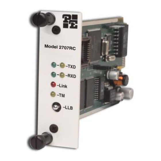
NetLink-E1™ Series front panel. Model 2707RC Link Figure 13. Model 2707RC front panel, showing LED indicators. When the unit sends a one, the TXD LED is green. When it sends a zero, the TXD LED is yellow. Moreover, the TXD LED is active only in active DS0 channels. -
Page 25: Local Loop Diagnostics
5.2 LOCAL LOOP DIAGNOSTICS The NetLink-E1 offers local loop diagnostics. Local loop is useful when isolating installation or performance problems. The Model 2707RC local loop is initiated via the front panel toggle switch labeled LLB. Operating local loopback (LLB) The local loopback (LLB) test checks the operation of the local NetLink- E1, and is performed separately on each unit. -
Page 26: Specifications
APPENDIX A SPECIFICATIONS Network Data Rate: 2.048 Mbps Network Connector: RJ-48C or dual BNC Nominal Impedance: 120 ohm (75 ohm available when using Pat- ton Model 1001RCM11575 rear card) DTE Interface: V.35, X.21 (DCE or DTE orientation), 10Base-T, Ethernet Line Coding: Selectable AMI or HDB3 Line Framing: G.703 (Unframed) -
Page 27: Cable Recommendations
24 AWG 83nf/mi or 15.72 pf/ft. .05165 Ohms/ft. To gain optimum performance from the Model 2707RC Series, please keep the following guidelines in mind: • Always use twisted pair wire—this is not an option. • Use twisted pair wire with a capacitance of 20pf/ft or less. -
Page 28: Factory Replacement Parts And Accessories
APPENDIX C FACTORY REPLACEMENT PARTS AND ACCESSORIES Patton Model # Description 2707RC/D/V E1/FE1 CSU/DSU Rack Card, X.21 Interface w/ DB15FS/RJ48C rear card 2707RC/B/B E1/FE1 CSU/DSU Rack Card, RS530\ Interface with DB25F/RJ48C Rear Card 2707RC/A/I E1/FE1 CSU/DSU Rack Card, V.35 Interface with M/... -
Page 29: E1 Interface Pin Assignment
APPENDIX D E1 INTERFACE PIN ASSIGNMENT RJ-48C E1 (DS0) NETWORK INTERFACE (FEMALE MODULAR JACK) Pin # Signal RX Data (RING) From Network RX Data (TIP) TX Data (RING) To Network TX Data (TIP) -
Page 30: Interface Pin Assignment
APPENDIX E V.35 INTERFACE PIN ASSIGNMENT M/34 CONNECTOR, TERMINAL INTERFACE Pin # Signal GND (Earth Ground/Shield) SGND (Signal Ground) CTS (DCE Source) DSR (DCE Source, Always On) CD (DCE Source) LL (Local Loop, DTE Source) TM (Test Mode Indicator, DCE Source) RL (Remote Loop, DTE Source) TD (Transmit Data +, DTE Source) RD (Receive Data +, DCE Source) -
Page 31: Eia-530 Interface Pin Assignment
APPENDIX F EIA-530 INTERFACE PIN ASSIGNMENT DB-25 FEMALE CONNECTOR, TERMINAL INTERFACE Pin # Signal FG (FrameGround) TD (Transmit Data-A, DTE Source) RD (Receive Data-A, DCE Source) RTS (Request to Send-A, DTE Source) CTS (Clear to Send-A, DCE Source) DSR (Data Set Ready-A, DCE Source) SGND (Signal Ground) CD (Carrier Detect-A, DCE Source) RC/ (Receiver Clock-B, DCE Source) -
Page 32: Interface Pin Assignment
APPENDIX G X.21 INTERFACE PIN ASSIGNMENT (DB-15 FEMALE CONNECTOR) (DTE /DCE CONFIGURATION) Pin # Signal Frame Ground T (Transmit Data-A) C (Control-A) R (Receive Data-A) I (Indication-A) S (Signal Element Timing-A) BT (Byte Timing-A) SGND (Signal Ground) T/ (Transmit Data-B) C/ (Control-B) R/ (Receive Data-B) I/ (Indication-B)
Need help?
Do you have a question about the 2707RC and is the answer not in the manual?
Questions and answers