Sign In
Upload
Manuals
Brands
Patton electronics Manuals
Network Hardware
ForeFront 2616RC
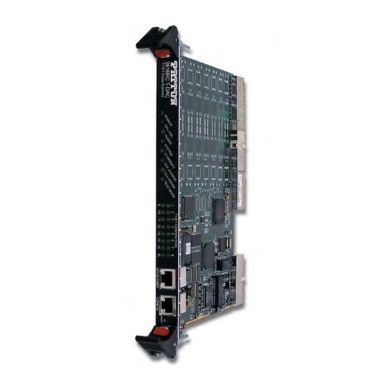
Patton electronics ForeFront 2616RC Manuals
Manuals and User Guides for Patton electronics ForeFront 2616RC. We have
4
Patton electronics ForeFront 2616RC manuals available for free PDF download: Administrator's Reference Manual, User Manual, Getting Started Manual, Specifications
Patton electronics ForeFront 2616RC Administrator's Reference Manual (315 pages)
T1/E1 TDM Digital Access Concentrator (T-DAC); G.SHDSL TDM Digital Access Concentrator (T-DAC); iDSL TDM T-DAC
Brand:
Patton electronics
| Category:
Network Hardware
| Size: 7 MB
Table of Contents
Table of Contents
4
About this Guide
30
Audience
30
Structure
30
Conventions Used in this Document
31
General Conventions
31
Text Conventions
31
Mouse Conventions
32
Precautions
31
Introduction
33
Chapter 1 Introduction
34
Introduction
34
Logging into the HTTP/HTML Web Management Windows
34
T-DAC Login Window
34
HTTP/HTML and SNMP Object Format
35
Saving HTTP/HTML Object Changes
35
Home
36
Chapter 2 Home
37
Introduction
37
HOME Window for Model 2616RC
37
HOME Window for Model 3096RC
38
HOME Window for Model 3196RC
38
Product Information Box
40
HOME Window Panes (Model 3096RC Version Shown)
40
Product Information Section of HOME Window (Model 3096RC Version Shown)
40
Operating Status Variables
41
Chassis Address (Cpcishelfaddr)
41
CPU Idle (Boxidletime)
41
Number of T1/E1 Ports (Boxegresscount)
41
Running Since Last Boot (Sysuptime)
41
Slot Address (Cpcislotid)
41
STATUS Menu (Model 3096RC Version Shown)
41
Current Card State (Alarmboxstate)
42
Total Card Alarms (Alarmtotal)
42
Operator Actions
42
Hard Reset (Hardreset(2))
42
Record Current Configuration (Storeconfig(1))
42
Operator Actions Buttons
42
Set Factory Default Configuration (Forcedefaultconfig(3))
43
Import/Export
44
Introduction
45
Export Current Flash Configuration
45
Import/Export Main Window (Model 3096RC Version Shown)
45
Import Flash Configuration from File
47
Alarms
48
Chapter 4 Alarms
49
Introduction
49
Alarm System Overview Window
49
Sample Alarm Indications
51
Alarm System Configuration Window
51
Alarms Management Windows
52
Alarm System Configuration Window
52
Alarms Management Diagram
52
Alarm Syslog Priority (Syslogalarmpriority)
53
Board Temperature Threshold (Boxalarmtemperature)
53
Modify Parameters and Modify Severity Links on Alarm System Overview Window
53
Alarm Trap Manager 1 through 4 (Alarmtrapip0-Alarmtrapip3)
54
Alarm Severity Configuration
54
DS0 Mapping
56
Chapter 5 DS0 Mapping
58
Introduction
58
DS0 Mapping Overview Window
58
DS0 Mapping Overview Main Window
59
DS0 Mapping Diagram
59
DS0 Mapping and In-Band Management
60
Non-Blocking System Constraints with In-Band Management
60
System Design Considerations and Guidelines
60
DS0 Fallback Configuration Window
61
Fallback Help Button
61
Watch Port Number (Daxwatchportgshdsl)
62
Watch Port Slots (Daxwatchslot)
62
Watch Port Type (Daxwatchtypegshdsl)
62
Watch the Following Ports for a Failure State
62
Fallback Mapping Help Window
62
Slot Numbering Examples
63
In Case of Failure, Switch to the Following Port
63
Fallback Port Number (Daxfallbackportgsds)
64
Fallback Port Number (Daxfallbackportgshdslh11)
64
Fallback Port Slots (Daxfallbackslot)
64
Fallback Port Type (Daxfallbacktypegshdsl)
64
Fallback Port Type Fromh110(0) (Daxfallbacktypegshdslh110)
64
DS0 Fallback ID (DAX Fallback ID) Window
65
Fallback Mapping ID
65
Fallback Port Slots (Daxfallbacksloth110)
65
Port Fallback Table
65
Recovery Type (Daxfallbackrecovery)
65
Viewing the DS0 Fallback ID Window
65
Deleting a Fallback Mapping
66
Force Recovery Button
66
Display Option Parameter
66
Mapping Help
67
Configuring Static Connections Using the Long Form
67
Device Type a (Daxdevicetypetogshdsl)
67
DACS Help Information Window
67
Device Type B (Daxdevicetypefromgshdsl) (Daxdevicetyperxgshdsl)
68
Device Number a (Daxdevicenumbertogshdsl) and Device Number B (Daxdevicenumberfromgshdsl) (Daxdevicenumberrxgshdsl)
68
Device Slots a and B (Daxdeviceslotto) (Daxdeviceslotfrom)
69
Slot Numbering Examples
69
Defining DS0 Mappings Using the Command Line Interface (CLI)
70
Slot Numbering Examples
71
Saving a DS0 Mapping Definition
72
Defined Mappings Table (Static Connections)
72
Fallback
72
ID (Daxconnectionid)
72
Port a
73
Port B
73
Slots a
73
Slots B
73
Type a
73
Type B
73
DS0 Connection ID (DAX Connection ID) Window
73
Viewing the DS0 Connection ID Window
73
Deleting a DS0 Mapping
74
System Clocking
75
Chapter 6 System Clocking
76
Introduction
76
System Clocking Configuration Window
77
System Clocking Configuration Table
77
Clock Reference (Sysgsclockmode)
78
Main Reference (Sysgshdslclockmainref) and Fallback Reference (Sysgshdslclockfallbackref)
79
Clocking Scheme for Master and Secondary Cards
79
System Clocking Configuration Window
80
Available Sources for T-DACS for Main and Fallback Reference Clocks
80
Clocking Status (Sysdaxclockfailure)
81
Fallback Indication (Daxfallbackind)
81
Clock Status
81
Clock Status: Alarms Present Indication
81
Enable/Disable Fallback System
82
Enable/Disable Clock Auto Recover System
82
Saving Your Work
82
Immediate Actions Buttons
83
System Clocking Help Window
83
Ethernet
84
Chapter 7 Ethernet
85
Introduction
85
Ethernet Overview Window
85
State (Boxetherastate)
85
Primaryipaddress (Boxetheraprimaryipaddress)
86
Primaryipmask (Boxetheraprimaryipmask)
86
Primaryipfilters (Boxetheraprimaryipfilters)
86
Secondaryipaddress (Boxetherasecondaryipaddress)
86
Secondaryipmask (Boxetherasecondaryipmask)
86
Secondaryipfilters (Boxetherasecondaryipfilters)
86
Technique (Boxetheratechnique)
86
Ethernet Statistics Window
87
Alignment Errors (Dot3Statsalignmenterrors)
87
FCS Errors (Dot3Statsfcserrors)
87
Single Collision Frames (Dot3Statssinglecollision Frames)
87
Multiple Collision Frames (Dot3Statsmultiplecollisionframes)
87
SQE Test Errors (Dot3Statssqetesterrors)
87
Deferred Transmissions (Dot3Statsdeferredtransmissions)
87
Late Collisions (Dot3Statslatecollisions)
87
Excessive Collisions (Dot3Statsexcessivecollisions)
87
Other Errors (Dot3Statsinternalmactransmiterrors)
88
Carrier Sense Errors (Dot3Statscarriersenseerrors)
88
Received Frames too Long (Dot3Statsframetoolongs)
88
Other Received Errors (Dot3Statsinternalmacreceiveerrors)
88
Chip Set ID (Dot3Statsetherchipset)
88
Ethernet Configuration Window
88
State (Boxetherastate)
88
Primary IP Settings
89
Primaryipaddress (Boxetheraprimaryipaddress)
89
Primaryipfilters (Boxetheraprimaryipfilters)
89
Primaryipmask (Boxetheraprimaryipmask)
89
Secondary IP Settings
89
Secondaryipaddress (Boxetherasecondaryipaddress)
89
Secondaryipmask (Boxetherasecondaryipmask)
89
Filter ID Number Location in IP Filtering Overview Window
89
Secondaryipfilters (Boxetherasecondaryipfilters)
90
Technique (Boxetheratechnique)
90
Frame Relay
91
Chapter 8 Frame Relay
93
Introduction
93
Configuring a Frame Relay Link
93
T1/E1 Port and DS0 Selection
93
The Frame Relay Main Window
94
Frame Relay Main Window
94
Link X (Frdlcmiifindex)
95
Data Overflow (Framerelrxdataoverflow)
95
HDLC Statistics on Link
95
No Buffers Available (Framerelrxnobufferavailable)
95
Receive (Bits/Sec) (Framerelrxoctets)
95
Status: X (Framerelstatus)
95
Transmit (Bits/Sec) (Framereltxoctets)
95
Aborts (Framerelrxabort)
96
Bad CRC (Framerelrxbadcrc)
96
Invalid Frames (Framerelrxinvalidframe)
96
LINK Resets (Framerelresets)
96
Message Ends (Framerelrxmessageends)
96
Overflow (Framerelrxoverflow)
96
Packets too Long (Framerelrxpackettoolong)
96
Produce Status Change Trap (Frtrapstate)
96
Tx Underrruns (Framereltxunderrun)
96
DLMI Window
96
Data Link Protocol (Frdlcmiaddress)
97
DLCI Length (Frdlcmiaddresslen)
97
Polling Interval (T391)(Frdlcmipollinginterval)
97
Signalling (Frdlcmistate)
97
DLMI Window
97
Full Enquiry Interval (N391)(Frdlcmifullenquiryinterval)
98
Error Threshold (N392)(Frdlcmierrorthreshold)
98
Monitored Events (N393)(Frdlcmimonitoredevents)
98
Multicast Service (Frdlcmimulticast)
98
Max Virtual Circuits (Frdlcmimaxsupportedvcs)
98
LMI Interface (Frdlcmiinterface)
98
Bidirectional Polling (Frdlcmipollingbidir)
98
Polling Verification (T392)(Frdlcmipollingverification)
98
DLCI Window
98
DLCI (Frcircuitdlci)
99
Interface # (Frameipinterfacenum)
99
State (Frcircuitstate)
99
Committed Burst (Bits) (Frcircuitcommitedburst)
100
Congestion (Frameenablecongestion)
100
Excess Burst (Bits) (Frcircuitexcessburst)
100
IP Address (Frameipaddr)
100
Throughput (Bits) (Frcircuitthroughput)
100
G.SHDSL (Model 3096RC)
101
Chapter 9 G.SHDSL (Model 3096RC)
103
Introduction
103
G.SHDSL Port Configuration Window
103
G.SHDSL Port Summary Status
104
Operator Action Buttons
105
G.SHDSL Port Configuration Window
105
G.SHDSL Port Status
106
Circuit ID (Gshdslcircuitid)
106
Port # (Gshdslportnum)
106
Clearing an Error Condition
107
State (Gshdslstate)
107
Hard Reset this Port Button
107
Color-Coded Port Status Indicators
108
Desired State (Gshdsldesirestate)
108
Test Mode (Sdsltmselection)
108
Color-Coded Port Status Example
108
Local Loopback
109
Remote Serial Loopback
109
Test Pattern (Gshdslpattselect)
110
Remote Ethernet Loopback
110
Line Loopback
110
Payload Rate (Gshdslpayloadrate)
112
Error Code (Gshdslerrorcode)
112
Saving Your Work
112
G.SHDSL Port Details Window
113
Operator Action Buttons
114
Port # Links
114
G.SHDSL Web Management Windows Map
114
Operator Action Buttons Section of the G.SHDSL Port Details Window
114
G.SHDSL Port Status and Statistics Tables
116
General Info Table
116
G.SHDSL Port Status and Statistics Sections of the G.SHDSL Port Details Window
116
Activation State Info Table
117
Fifo Info Table
118
Data Path Info Table
118
History Details Table
119
Port Configuration Tables
120
Cancel Button
121
Change Config Button
121
CO Configuration Table
121
CPE Configuration Table
123
Additional CPE Parameters
124
CPE Line Loopback
124
Hardware Loop Status Parameters
125
CPE Local Loopback
125
Saving Your Work
126
Hard Reset this Port Button
126
CPE Remote Loopback
126
G.SHDSL Port History of Near-End Performance Window
127
History of Near-End Performance Window
127
Links to and from the G.SHDSL Port History of Near End Performance Window
127
Back to System History Page Hyperlink
128
To Port Details Page Hyperlink
128
Error Statistics Table
128
System History Overview Window (Model 3096RC Shown)
128
G.SHDSL Line Provision Window
129
Back Button
129
Refresh Current Page Button
129
Calculate Best Line Rate Button
130
Cancel Button
130
Idsl (Model 3196RC)
131
Chapter 10 Idsl (Model 3196RC)
132
Introduction
132
Idsl Port Configuration Window
132
Idsl Port Summary Status
133
Idsl Port Configuration Window
133
Operator Action Buttons
134
Idsl Port Status
134
Port Number (Idslportnum)
134
Circuit ID (Idslcircuitid)
135
Clearing an Error Condition
135
Current State (Idslcurrentstate)
135
Color-Coded Port Status Indicators
136
Desired State (Idsldesirestate)
136
Test Mode (Idsltmselection)
136
Color-Coded Port Status Example
136
Local Loopback
137
Remote Serial Loopback
137
Test Pattern (Idslpattselect)
138
Line Loopback
138
CPE Device (Idslremotemodelcode)
139
CPE Circuit ID
139
Saving Your Work
139
Idsl Port Details Window
140
Operator Action Buttons
141
Port # Links
141
Operator Action Buttons Section of the Idsl Port Details Window
141
Idsl Port Status and Statistics Tables
142
Idsl Port Status Table
142
Idsl Port Status and Port Statistics Sections of the Idsl Port Details Window
142
Idsl Port Statistics Table
143
CPE Information and Configuration
144
CPE Configuration
144
CPE Information
144
CPE Information Window
144
Idsl Near End Performance Interval
145
Near End Performance in the Current 15 Minute Interval
146
Idsl Port History of Near End Performance Window
146
Back to System History Page Hyperlink
147
To Port Details Page Hyperlink
147
Error Statistics Table
147
System History Overview Window (Model 3196RC Shown)
147
Idsl Alarm Thresholds Per 15 Minute Interval
148
In-Band Management
149
Chapter 11 In-Band Management
151
Overview
151
Introduction
151
When to Use In-Band Management
152
In-Band Management Overview Window
153
11 • In-Band Management
153
In-Band Management Overview Window (Model 2616RC Shown)
153
Defining a T1/E1 Management Channel
154
Channels 1-16 Set to PPP
155
Example 1: T1/E1 Frame Relay Management Channel
156
Deleting the T1/E1 Management Channel
157
Example 2: T1/E1 Routed PPP Management Channel
158
Deleting the T1/E1 Management Channel
159
Example 3: T1/E1 Bridged PPP Management Channel
159
Deleting the T1/E1 Management Channel
160
Defining a Chassis (H.110) Management Channel
160
PPP-IPCP Chassis Management Channel
161
Direction
161
IP Address (Sysmgmtipaddress)
161
Name
161
Port
161
Default Gateway (Sysmgmtdefaultgateway)
162
Timeslot
162
Default Gateway Address Example
163
Example 1: Routed PPP (IPCP) Chassis Management Channel
164
Define Button
164
Define a Chassis Management Channel
164
Example 2: Bridged PPP (BCP) Chassis Management Channel
165
Defining a G.SHDSL Management Channel
167
IP Addresses-IPCP & BCP
167
Configure the Model 3096RC for a G.SHDSL In-Band Management Channel
168
Example 1: Configuring a BCP Bridged G.SHDSL Link for Management Traffic Only
169
Configure Model 3086 for an In-Band Management Channel
170
3096RC G.SHDSL Management Link Status
171
Example 2: Configuring an IPCP Routed G.SHDSL Link for Management Traffic Only
172
Configure Model 3086 for an In-Band Management Channel
173
3096RC G.SHDSL Management Link Status
174
The Chassis Management Channel Statistics Page
176
Connection ID (Sysmgmtconnectionid)
176
Deleting an H.110 In-Band Management Channel
176
H.110 In-Band Management Statistics
176
Connection Details
177
HDLC Statistics
177
IP Address (Sysmgmtipaddress)
177
LINK Resets (Sysmgmtresets)
177
Rx Port (Sysmgmtportrx)
177
Rx Timeslot (Sysmgmtslotrx)
177
Status (Sysmgmtstatus)
177
Transmit Octets (Sysmgmttxoctets)
177
TX Port (Sysmgmtporttx)
177
Tx Timeslot (Sysmgmtslottx)
177
Receive Bad Crcs (Sysmgmtrxbadcrc)
178
Receive Frames (Sysmgmtrxmessageends)
178
Receive Frames too Long (Sysmgmtrxpackettoolong)
178
Receive Invalid Frames (Sysmgmtrxinvalidframe)
178
Receive no Buffers Available (Sysmgmtrxnobufferavailable)
178
IP Routing Table Modifications
178
Recommended Troubleshooting if the Link Does Not Come up
178
Ip (Ip, Tcp, Udp, & Icmp)
179
Chapter 12 IP (IP, TCP, UDP, & ICMP)
183
Introduction
183
IP Overview Window
183
IP Overview Window
184
IP Overview Window and Related Windows
184
Hyperlinks
185
IP Parameters
185
Forwarding
185
Default Time-To-Live
186
Discarded for Address Errors
186
Discarded for Header Errors
186
Discarded for Unknown Protos
186
Discarded with no Errors
186
Forwarded Datagrams
186
IP Statistics
186
Out Requests
186
Total Datagrams Received
186
Total Deliveries
186
Discarded for no Routes
187
Fragmented Failed
187
Fragmented OK
187
Fragments Created
187
Of Reassembled Fragments
187
Out Discards
187
Reassembly Failures
187
Reassembly Timeout
187
Successfully Reassembled
187
Valid but Discarded
188
IP Configuration Window
188
Default Time-To-Live (Ipdefaultttl)
188
Forwarding (Ipforwarding)
188
IP Configuration
188
Saving Your Work
188
IP Addressing Overview Window
189
Entry Broadcast Address (Ipadentbcastaddr)
189
Entry Interface Index (Ipadentifindex)
189
Entry Subnet Mask (Ipadentnetmask)
189
IP Address Details Window
189
Entry Reassembly Maximum Size (Ipadentreasmmaxsize)
190
IP Routing Overview Window
190
Defined Routes
190
Destination (Genroutedest)
190
Cost (Genroutecost)
191
Gateway (Genroutegateway)
191
Interface (Genrouteifindex)
191
Mask (Genroutemask)
191
Protocol (Genrouteproto)
191
State (Routestate)
191
Advanced
192
Defined Routes
192
Destination (Iproutedest)
192
Gateway (Genroutegateway)
192
Interface (Genrouteifindex)
192
Mask (Iproutemask)
192
IP Route Details Window
193
Destination IP Address (Genroutedest)
193
Interface (Genrouteifindex)
193
Mask (Genroutemask)
193
Protocol (Genrouteproto)
193
Cost (Genroutecost)
194
Gateway (Genroutegateway)
194
Seconds Since Updated (Genrouteage)
194
State (Genroutestate)
194
Tag (Genroutetag)
194
IP Routing Table Window
194
Destination (Iproutedest)
195
Interface (Iprouteifindex)
195
Mask (Iproutemask)
195
Next Hop (Iproutenexthop)
195
Protocol (Iprouteproto)
195
Type (Iproutetype)
195
Info (Iprouteinfo)
196
IP Address Translation Overview Window
196
Defined Address Correlations
196
Interface (Ipnettomediaifindex)
196
Define a New Address Correlation
197
Net Address (Ipnettomedianetaddress)
197
Physical (Ipnettomediaphysaddress)
197
Type (Ipnettomediatype)
197
TCP Overview Window
198
TCP Windows Map
198
Details
199
TCP Parameters
199
Active Opens (Tcpactiveopens)
199
Attempt/Fails (Tcpattemptfails)
199
Maximum Connections (Tcpmaxconn)
199
Passive Opens (Tcppassiveopens)
199
Retransmit-Timeout Algorithm (Tcprtoalgorithm)
199
Retransmit-Timeout Maximum (Tcprtomax)
199
Retransmit-Timeout Minimum (Tcprtomin)
199
TCP Statistics
199
Current ESTABLISHED (Tcpcurrestab)
200
Total Received (Tcpinsegs)
200
Total Received in Error (Tcpinerrs)
200
Total Retransmitted (Tcpretranssegs)
200
Total Sent (Tcpoutsegs)
200
Total Sent W/Rst Flag (Tcpoutrsts)
200
TCP Details Window
200
Local Port (Tcpconnlocalport)
200
Remote Address (Tcpconnremaddress)
200
TCP Connections
200
Remote Port (Tcpconnremport)
201
State (Tcpconnstate)
201
UDP Overview Window
201
Datagrams Received (Udpindatagrams)
202
Datagrams Received with no Delivery (Udpinerrors)
202
Datagrams Received with no Ports (Udpnoports)
202
Datagrams Sent (Udpoutdatagrams)
202
Local Address (Udplocaladdress)
202
Local Port (Udplocalport)
202
UDP Listener Table (Udptable)
202
UDP Statistics
202
UDP Overview Window
202
ICMP Overview Window
203
ICMP Parameters
203
ICMP Redirects (Boxblockicmpredirects)
203
Destinations Unreachable (Icmpindestunreachs, Icmpoutdestunreachs)
204
ICMP Statistics
204
Total ICMP Datagrams Received (Icmpinmsgs)
204
Total ICMP Datagrams Sent (Imcpoutmsgs)
204
W/Errors (Icmpinerrors, Icmpouterrors)
204
Echo Replys (Icmpinechoreps, Icmpoutechoreps)
205
Echos (Icmpinechos, Icmpoutechos)
205
Parameter Problems (Icmpinparmprobs, Icmpoutparmprobs)
205
Redirects (Icmpinredirects, Icmpoutredirects)
205
Source Quenchs (Icmpinsrcquenchs, Icmpoutsrcquenchs)
205
Time Stamps (Icmpintimestamps, Icmpintimestamps)
205
Times Exceeded (Icmpintimeexcds, Icmpouttimeexcds)
205
Address Mask Replys (Icmpinaddrmasksreps) (Icmpoutaddrmasksreps)
206
Address Mask Requests (Icmpinaddrmasks) (Icmpoutaddrmasks)
206
Time Stamp Replys (Icmpintimestampsreps) (Icmpouttimestampsreps)
206
IP Filtering
207
Chapter 13 IP Filtering
208
Introduction
208
IP Filtering Overview Window
208
Defined Filters
208
Define a New Filter
208
Defining a New Filter
209
Deleting a Filter
209
IP Filter Configuration Window
209
Name (Filteripname)
209
ID Name Hyperlink
209
Filter IP Parameters Window
209
Direction (Filteripdirection)
210
Action (Filteripaction)
210
Source IP
210
Comparison (Filteripsourceaddresscmp)
210
Address (Filteripsourceip)
211
Address(Filteripdestinationip)
211
Comparison (Filteripdestinationaddresscmp)
211
Comparison (Filteripsourceportcmp)
211
Destination IP
211
Mask (Filteripsourcemask)
211
Mask(Filteripdestinationmask)
211
Port (Filteripsourceport)
211
Source Port
211
Comparison (Filteripdestinationportcmp)
212
Deleting a Filter
212
Destination Port
212
Port (Filteripdestinationport)
212
Protocol (Filteripprotocol)
212
TCP Established (Filteriptcpestablished)
212
An Example of Using a Filter
212
Ppp
215
Chapter 14 PPP
218
Introduction
218
T1/E1 Port and DS0 Selection
218
T1/E1 Link Activity Overview Window
218
PPP Window
220
PPP ID (Pppindex)
220
State (Pppactstate)
220
User (Pppauthenticationusername)
220
Default Details
221
Hyperlinks
221
IP Address (Pppserviceipaddress)
221
IP Mask (Pppserviceipmask)
221
Modify Default
221
Default Packet Settings Window
221
IP Address
222
Default Packet Settings Window
222
Authentication Side (Pppdefaultauthenticationside)
222
Authentication Technique (Pppdefaultauthenticationtechnique)
222
Modify Default Settings Hyperlink
222
Modify Default Packet Settings Window
222
Authentication Username (Pppdefaultauthenticationusername)
223
Authentication Password (Pppdefaultauthenticationpassword)
223
MRU (Pppdefaultinitialmru)
223
Link Compression (Pppdefaultlinkcompression)
223
Allow Magic Number Negotiation(Pppdefaultmagicnumber)
223
Compression (Pppdefaultipcompression)
223
Modify Default Packet Settings Window
223
Allow Magic Number Negotiation(Pppdefaultmagicnumber)
224
Authentication Password (Pppdefaultauthenticationpassword)
224
Authentication Side (Pppdefaultauthenticationside)
224
Authentication Technique (Pppdefaultauthenticationtechnique)
224
Authentication Username (Pppdefaultauthenticationusername)
224
Link Compression (Pppdefaultlinkcompression)
224
MRU (Pppdefaultinitialmru)
224
Compression (Pppdefaultipcompression)
225
PPP Link Window
225
HDLC Statistics on Link
225
Link (Frdlcmiifindex)
225
RECEIVE (Framerelrxoctets)
225
Status (Framerelstatus)
225
Transmit(Framereltxoctets)
225
Aborts (Framerelrxabort)
226
Bad Crcs (Framerelrxbadcrc)
226
Data Overflow (Framerelrxdataoverflow)
226
Invalid Frames (Framerelrxinvalidframe)
226
LINK Resets (Framerelresets)
226
Message Ends (Framerelrxmessageends)
226
No Buffers Available (Framerelrxnobufferavailable)
226
Overflow (Framerelrxoverflow)
226
Packets too Long (Framerelrxpackettoolong)
226
Tx Underruns (Framereltxunderrun)
226
Allow Magic Number Negotiation (Pppmagicnumber)
227
Authentication Password (Pppauthenticationpassword)
227
Authentication Side (Pppauthenticationside)
227
Authentication Username (Pppauthenticationusername)
227
IP Address (Pppserviceipaddress)
227
IP Compression (Pppipcompression)
227
IP Force Next Hop (Pppforcenexthop)
227
IP Mask (Pppserviceipmask)
227
Link Compression (Ppplinkcompression)
227
MRU (Pppinitialmru)
227
Bad Address (Pppstatbadaddresses)
228
Bad Controls (Pppstatbadcontrols)
228
LCP Authentication (Pppstatlcpauth)
228
LCP Statistics
228
Local ACC Map (Pppstatlocaltopeeraccmap)
228
Local MRU (Pppstatlocalmru)
228
Packets too Long (Pppstatpackettoolongs)
228
PPP Statistics
228
Remote ACC Map (Pppstatpeertolocalaccmap)
228
Remote MRU (Pppstatremotemru)
228
Local AC Comprsn (Pppstatlocaltoremoteaccomp)
229
Local Frame Check Seq. Size (Pppstattransmitfcssize)
229
Local PPP Protocol Comprsn (Pppstatlocaltoremoteprotcomp)
229
Remote AC Comprsn (Pppstatremotetolocalaccomp)
229
Remote Frame Check Seq. Size (Pppstatreceivefcssize)
229
Remote PPP Protocol Comprsn (Distatremotetolocalprotcomp)
229
Data Statistics
230
IP Statistics
230
Local Max Slot ID (Pppiplocalmaxslotid)
230
Local VJ Protocol Comprsn (Pppiplocaltoremotecompprot)
230
Octets Received (Pppactreceivedoctets)
230
Octets Sent (Pppactsentoctets)
230
Operational Status (Pppipoperstatus)
230
Packets Sent (Pppactsentdataframes)
230
Remote Max Slot ID (Pppipremotemaxslotid)
230
Remote VJ Protocol Comprsn (Pppipremotetolocalcompprot)
230
Modify Link Configuration Window
231
Authentication Technique (Pppauthenticationtechnique)
231
Link Configuration
231
PPP Protocol (Pppdesiredfunction)
231
Authentication Password (Pppauthenticationpassword)
232
Authentication Side (Pppauthenticationside)
232
Authentication Username (Pppauthenticationusername)
232
IP Address (Pppserviceipaddress)
232
IP Compression (Pppipcompression)
232
IP Force Next Hop (Pppforcenexthop)
232
IP Mask (Pppserviceipmask)
232
Link Compression (Ppplinkcompression)
232
MRU (Pppinitialmru)
232
Security Level (Pppaccesslevel)
232
Allow Magic Number Negotiation (Pppmagicnumber)
233
RIP Version 2
234
Chapter 15 RIP Version 2
235
Introduction
235
RIP Version 2 Overview Window
235
RIP Summary Statistics
235
Defined RIP Addresses
236
Define a New RIP Address
236
RIP Version 2 Statistics
237
Subnet IP Address (Rip2Ifstataddress)
237
RIP Version 2 Statistics Window
237
Bad Packets (Rip2Ifstatrcvbadpackets)
238
Bad Routes (Rip2Ifstatrcvbadroutes)
238
Sent Updates (Rip2Ifstatsentupdates)
238
Status (Rip2Ifstatstatus)
238
RIP Version 2 (Configuration) Window
238
Address (Rip2Ifconfaddress)
239
Authentication Key (Rip2Ifconfauthkey)
239
Authentication Type (Rip2Ifconfauthtype)
239
Domain (Rip2Ifconfdomain)
239
Metric (Rip2Ifconfdefaultmetric)
239
Status (Rip2Ifconfstatus)
239
Advertisement
Patton electronics ForeFront 2616RC User Manual (80 pages)
T1/E1 TDM-Digital Access Concentrator (T-DAC)
Brand:
Patton electronics
| Category:
Network Hardware
| Size: 3 MB
Table of Contents
User Manual
1
Table of Contents
4
About this Guide
10
Audience
10
Structure
10
Precautions
11
Typographical Conventions Used in this Document
12
General Conventions
12
Mouse Conventions
12
Introduction
13
Model 2616RC T1/E1 T-DAC Overview
14
Model 2616RC T-DAC
14
Hardware Overview
15
Lan
15
Wan
15
Model 2616RC T-DAC Features
15
Altitude
16
Central Processing Unit
16
Humidity
16
Management Services
16
Physical Dimensions
16
Power System
16
RS-232 Control Port
16
System Timing
16
Temperature
16
Model 2616RC Front Panel Leds
17
LED Display
18
LED Definitions
18
Hardware Installation
19
Chapter 2 Hardware Installation
20
Introduction
20
Unpacking the Model 2616RC T-DAC
20
T-DAC Blades Installation
20
Alignment/Esd Pin and Card Handle
21
Cable Installation
22
Connecting the 10/100Base-T Ethernet Port to an Ethernet Switch or Hub
22
Connecting the Ethernet Ports
22
Model 2616RC Network and Configuration Ports
22
Connecting the 10/100Base-T Ethernet Port to an Ethernet-Capable Workstation or PC
23
Connecting the EIA-561 RS-232 Configuration Port (DCE Configured)
23
Ethernet RJ-45 Pin and Signal Definitions for T-DAC
23
Cross-Over RJ-45-To-RJ-45 Ethernet Cable Diagram
23
DB-9-To-RJ-45 Cable Diagram
23
Connecting the T1/E1 WAN Ports
24
68-Pin SCSI to 8 RJ-45 Connectors Cable
24
SCSI-To-RJ45 6-Foot WAN Cable
24
WAN Cable's 68-Pin SCSI Connector
25
RJ-45 Plug
25
RJ-45 Plug Pin-Out
25
68-Pin SCSI to Open End Cable
26
SCSI-To-Open-End WAN Cable
26
68-Pin SCSI Connector
26
WAN Cable's 68 Non-Terminated Twisted-Pairs
27
Installing the WAN Cable to a Punch-Down Block
28
Punch-Down Block Wiring
28
68-Pin SCSI to Open End, 6 Foot Cable (Part #10-3096TM68-6)-Obsolete
29
68-Pin SCSI to 64-Pin Female Telco (Part #10-3096TM68/64-6)
29
SCSI-To-Open-End 6-Foot WAN Cable (Obsolete)
29
Completing the Hardware Installation
30
Configuring the T-DAC for Operation
31
Chapter 3 Configuring the T-DAC for Operation
32
Introduction
32
Configuration Prerequisites
32
Initial Configuration through the RS-232 Control Port
33
Connecting the DB9-RJ45 Adapter with the Included Cable
33
Model 2616RC Interface Ports
33
Setting up the Hyperterminal (or Similar Program) Session
34
Connection Description Window
34
Connect to Window
34
COM1 Properties Window
35
Terminal Keys Configuration
35
Login Window
36
VT-100 Top Level Management Window
36
Using a Browser to Complete Model 2616RC Configuration
37
Ethernet Configuration Window
37
Displaying the T-DAC 2616RC Web Administration Pages
38
Home
38
2616RC Configuration Menu Home Page
38
HOME Page Window Panes
39
Operator Actions Buttons
39
Configuring the Default Gateway
40
IP Routing Information Page
40
Configuring the System Clocking Parameters
41
IP Routing Information Window
41
System Clocking Configuration Page, Example 1
42
System Clocking Configuration Page, Example 2
43
Clock Reference Submit Query Button
43
Configuring the DS0 Mapping
44
DS0 Mapping Overview Window
44
Display Option Menu
44
Configuring Line Settings and Signaling for E1
46
Accessing the Line Interface Settings
46
T1/E1 Link Activity Overview Page
46
Configuring the E1 Line Interface Settings
47
T1/E1 Link Activity Ports 1 - 4 Page
47
WAN Circuit Configuration Page, Line Interface Settings
47
Line Type Pull-Down Menu
48
Line Coding Pull-Down Menu with Dsx1Hdb3(3) Selected
48
Line Build out Pull-Down Menu with E1Pulse(1) Selected
48
Configuring Line Settings and Signaling for T1
49
Accessing the Line Interface Settings
49
E1 ALARMS PRESENT Indicator
49
T1/E1 Link Activity Overview Page
49
T1/E1 Link Activity Ports 1 - 4 Page
49
Configuring the T1 Line Settings
50
WAN Circuit Configuration Page, Line Interface Settings
50
Line Type Pull-Down Menu with Dsx1Esf(2) Selected
50
Line Coding Pull-Down Menu with Dsx1B8Zs(2) Selected
51
Line Build out Pull-Down Menu with T1Pulse0Db(1) Selected
51
T1 ALARMS PRESENT Indicator on T1/E1 LINK ACTIVITY Page
51
Enabling/Disabling the Alarm Card
52
Alarm Card Information Window
52
Saving Your Configuration
53
Backing up Your Configuration Parameters
53
2616RC Configuration Menu Home Page
53
IMPORT/EXPORT Page
54
Backing up the Configuration Store in Flash Memory
55
Example T-DAC Flash Memory Configuration File Displayed in a Browser
55
Completing the Installation
56
Saving the Access Server Flash Memory Configuration Data as a Text File
56
Operation and Shutdown
58
Introduction
59
Activating the Model 2616RC
59
De-Activating the Model 2616RC
59
Troubleshooting and Maintenance
60
Symptoms
61
Patton electronics ForeFront 2616RC Getting Started Manual (80 pages)
T1/E1 TDM-Digital Access Concentrator (T-DAC)
Brand:
Patton electronics
| Category:
Network Hardware
| Size: 2 MB
Table of Contents
Table of Contents
4
About this Guide
10
Audience
10
Structure
10
Precautions
11
Typographical Conventions Used in this Document
12
General Conventions
12
Mouse Conventions
12
Introduction
13
Model 2616RC T1/E1 T-DAC Overview
14
Model 2616RC T-DAC
14
Hardware Overview
15
Lan
15
Wan
15
Model 2616RC T-DAC Features
15
Altitude
16
Central Processing Unit
16
Humidity
16
Management Services
16
Physical Dimensions
16
Power System
16
RS-232 Control Port
16
System Timing
16
Temperature
16
Model 2616RC Front Panel Leds
17
LED Display
18
Hardware Installation
19
Chapter 2 Hardware Installation
20
Introduction
20
Unpacking the Model 2616RC T-DAC
20
T-DAC Blades Installation
20
Alignment/Esd Pin and Card Handle
21
Cable Installation
22
Connecting the 10/100Base-T Ethernet Port to an Ethernet Switch or Hub
22
Connecting the Ethernet Ports
22
Connecting the 10/100Base-T Ethernet Port to an Ethernet-Capable Workstation or PC
23
Connecting the EIA-561 RS-232 Configuration Port (DCE Configured)
23
Cross-Over RJ-45-To-RJ-45 Ethernet Cable Diagram
23
DB-9-To-RJ-45 Cable Diagram
23
Connecting the T1/E1 WAN Ports
24
68-Pin SCSI to 8 RJ-45 Connectors Cable
24
SCSI-To-RJ45 6-Foot WAN Cable
24
WAN Cable's 68-Pin SCSI Connector
25
RJ-45 Plug
25
RJ-45 Plug Pin-Out
25
68-Pin SCSI to Open End Cable
26
SCSI-To-Open-End WAN Cable
26
68-Pin SCSI Connector
26
WAN Cable's 68 Non-Terminated Twisted-Pairs
27
Installing the WAN Cable to a Punch-Down Block
28
Punch-Down Block Wiring
28
68-Pin SCSI to Open End, 6 Foot Cable (Part #10-3096TM68-6)-Obsolete
29
68-Pin SCSI to 64-Pin Female Telco (Part #10-3096TM68/64-6)
29
SCSI-To-Open-End 6-Foot WAN Cable (Obsolete)
29
Completing the Hardware Installation
30
Configuring the T-DAC for Operation
31
Chapter 3 Configuring the T-DAC for Operation
32
Introduction
32
Configuration Prerequisites
32
Configuring the T-DAC for Operation
32
Initial Configuration through the RS-232 Control Port
33
Connecting the DB9-RJ45 Adapter with the Included Cable
33
Model 2616RC Interface Ports
33
Setting up the Hyperterminal (or Similar Program) Session
34
Connection Description Window
34
Connect to Window
34
COM1 Properties Window
35
Login Window
36
VT-100 Top Level Management Window
36
Using a Browser to Complete Model 2616RC Configuration
37
Displaying the T-DAC 2616RC Web Administration Pages
38
Home
38
HOME Page Window Panes
39
Operator Actions Buttons
39
Configuring the Default Gateway
40
IP Routing Information Page
40
Configuring the System Clocking Parameters
41
IP Routing Information Window
41
Clock Reference Submit Query Button
43
Configuring the DS0 Mapping
44
DS0 Mapping Overview Window
44
Display Option Menu
44
Configuring Line Settings and Signaling for E1
46
Accessing the Line Interface Settings
46
T1/E1 Link Activity Overview Page
46
Configuring the E1 Line Interface Settings
47
T1/E1 Link Activity Ports 1 - 4 Page
47
Line Type Pull-Down Menu
48
Line Coding Pull-Down Menu with Dsx1Hdb3(3) Selected
48
Line Build out Pull-Down Menu with E1Pulse(1) Selected
48
Configuring Line Settings and Signaling for T1
49
Accessing the Line Interface Settings
49
E1 ALARMS PRESENT Indicator
49
T1/E1 Link Activity Overview Page
49
T1/E1 Link Activity Ports 1 - 4 Page
49
Configuring the T1 Line Settings
50
Line Type Pull-Down Menu with Dsx1Esf(2) Selected
50
Line Coding Pull-Down Menu with Dsx1B8Zs(2) Selected
51
Line Build out Pull-Down Menu with T1Pulse0Db(1) Selected
51
T1 ALARMS PRESENT Indicator on T1/E1 LINK ACTIVITY Page
51
Enabling/Disabling the Alarm Card
52
Alarm Card Information Window
52
Saving Your Configuration
53
Backing up Your Configuration Parameters
53
IMPORT/EXPORT Page
54
Backing up the Configuration Store in Flash Memory
55
Completing the Installation
56
Operation and Shutdown
58
Introduction
59
Activating the Model 2616RC
59
De-Activating the Model 2616RC
59
Troubleshooting and Maintenance
60
Symptoms
61
Advertisement
Patton electronics ForeFront 2616RC Specifications (2 pages)
16-Port T1/E1 T-DAC Digital Cross Connect
Brand:
Patton electronics
| Category:
Network Hardware
| Size: 0 MB
Advertisement
Related Products
Patton electronics NetLink 2720 Series
Patton electronics 2450
Patton electronics 2500 Series
Patton electronics 2707RC
Patton electronics 2715
Patton electronics NetLink 2720/B
Patton electronics NetLink 2720/C
Patton electronics 2510
Patton electronics OnSite 2884
Patton electronics 2112-CO
Patton electronics Categories
Modem
Network Hardware
Network Router
Media Converter
Extender
More Patton electronics Manuals
Login
Sign In
OR
Sign in with Facebook
Sign in with Google
Upload manual
Upload from disk
Upload from URL