Advertisement
T-Series Climate
®
Changer
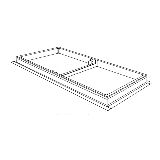
Roof Curb
Installation
Library
Product Section
Product
Model
Literature Type
Sequence
Date
File No.
Since the Trane Company has a policy of continuous product improvement, it reserves the right to change
specifications and designs without notice. The installation and servicing equipment referred to into this book-
let should be done by qualified experienced technicians.
CLCH-IN-18A
Service Literature
Air Handling
Central Station Air Handlers
T-Series Climate Changer
Installation
June 1999
CLCH-IN-18A 6/99
Part No. X39640529-02
01
Advertisement
Table of Contents

Related Manuals for Trane CLCH-IN-18A


Summary of Contents for Trane CLCH-IN-18A
-
Page 1: Roof Curb
Roof Curb Part No. X39640529-02 Since the Trane Company has a policy of continuous product improvement, it reserves the right to change specifications and designs without notice. The installation and servicing equipment referred to into this book- let should be done by qualified experienced technicians. - Page 2 RTWA-IOM-1A...
-
Page 3: Installation Considerations
For new building construction , the roof curb may INSTALLATION CONSIDERATIONS be installed as soon as the roof support members are in place. Trane recommends that the roof curb Before assembling or placing the roof curb in be placed directly on the roof support members position, consider the following for a proper and welded into place. - Page 4 Roof deck Figure 3 Pier Mount Detail Figure 6 Typical Installation of Roof Curb in New Construction 2x4 nailer Gasket Nail Counter flashing Figure 7 Detail Roof curb Flashing Roof/insulating mat’l 4x4 cant Roof insulation Piers Roof structure Roof deck CLCH-IN-18A...
-
Page 5: Assembly And Installation
NOTE: MATERIALS TO ATTACH TO THE ROOF CURB Figure 10 ARE TO BE SUPPLIED BY THE INSTALLER. GASKET Corner Splice Detail AND 2 X 4 NAILER ARE SUPPLIED BY TRANE. Inner corner angle Washer DO NOT OVERLAP COUNTER FLASHING OVER THE TOP OF THE ROOF CURB. - Page 6 (d) Install gasket along the perimeter of the pipe Trane require special attention, especially if a pipe chase roof curb and the gutter as shown in cabinet is ordered from Trane. A typical unit roof curb Figure 13 . The gasket for the gutter will run...
- Page 7 Figure 15 not include the 3 inches for each end of the unit base. Cross Sections Pipe cabinets ordered from Trane for field installation 1.945 require special attention with regard to joining the unit roof curb and pipe cabinet roof curb. A good joint will prevent any water management problems within the pipe cabinet.
- Page 8 Lp is the sum of the module length(s) covered by the pipe cabinet. .178 Refer to submittal. 2.942 Figure 18 Assembly q Figure 19 shows a right side view and isometric view of a fabricated gutter piece with detailed dimensions. CLCH-IN-18A...
-
Page 9: Ductwork Recommendations
Figure 19 Gutter views .625 .926 2.000 3.318 1.500 1st Module Last Module .658 2nd Module .658 .625 2.15 2.15 In addition, special consideration may be required to L is the fabricated gutter length. L = Lp + 1.316 inches. ensure that the weight of the unit does not crush the roof deck at those points where the deck is between DUCTWORK RECOMMENDATIONS... - Page 10 Both supply and return Figure 20 Typical Supply and Return Ductwork Coil space 3 Fan Vertical Return air diameters discharge Use line duct for all returns (1” thick, 6 lb density fiberglass recommended) CLCH-IN-18A...
Need help?
Do you have a question about the CLCH-IN-18A and is the answer not in the manual?
Questions and answers