Table of Contents
Advertisement
T-Series Climate
®
Changer
Central
Station Air Handlers
Installation
and
Maintenance
Manual
Library
Product Section
Product
Model
Literature Type
Sequence
Date
File No.
Draw-Thru and Blow-Thru Unit Sizes 3, 6, 8, 10, 12, 14, 17, 21, 25, 30,
35, 40, 50, 66, 80, and 100
Since the Trane Company has a policy of continuous product improvement, it reserves the right to change
specifications and designs without notice. The installation and servicing equipment referred to into this book-
let should be done by qualified experienced technicians.
CLCH-IM-16A
Service Literature
Air Handling
Central Station Air Handlers
T-Series Climate Changer
Installation/Maintenance
March 1999
CLCH-IM-16A 3/99
Part No. X39640516-01
2
Advertisement
Table of Contents

Related Manuals for Trane CLCH-IM-16A


Summary of Contents for Trane CLCH-IM-16A
- Page 1 35, 40, 50, 66, 80, and 100 Part No. X39640516-01 Since the Trane Company has a policy of continuous product improvement, it reserves the right to change specifications and designs without notice. The installation and servicing equipment referred to into this book-...
-
Page 2: Warning And Cautions
ATMOSPHERE IS BEING REDUCED DUE TO THE WARNING RELEASE OF CFC FULLY HALOGENATED COMPOUNDS. THE TRANE COMPANY URGES THAT ALL HVAC WARNING indicates a potentially hazardous SERVICERS WORKING ON TRANE EQUIPMENT, OR situation that could result in personal injury or death. -
Page 3: Table Of Contents
Table of Contents General Information ..........1 Unit Description ..........1 Operating Environment ........1 Unit Nameplates ..........1 Controls .............. 2 Receiving .............. 3 Storage Considerations ........3 Rigging and Handling .......... 4 Determine Unit Weights ........4 Lifting Instructions ..........12 Installation ............ -
Page 4: General Information
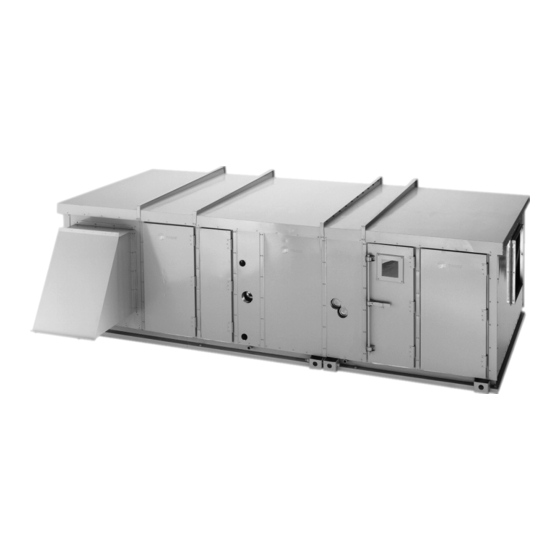
Trane T-Series Climate Changers ship as complete assemblies or sectional subassemblies. Some assembly is required when the units ship as subassemblies. Unit Description Operating Environment ® Trane T-Series Climate Changers are Central The T-Series Climate Changer (TSC) is an outdoor Station Air Handlers designed for a variety of air air handler. -
Page 5: Controls
A T-Series Climate Changer unit and/or field-installed manufacturer’s name, model number, and serial accessories that must be stored for a period of time number and contact your local Trane representative prior to being installed MUST be protected from the for assistance. -
Page 6: Receiving
It is the receiver’s responsibility to provide reasonable evidence that the concealed damage was not incurred after delivery. 4 Notify the Trane sales representative of the The T-Series Climate Changer can ship as individual damage and arrange for repair. Do not attempt to... -
Page 7: Rigging And Handling
Table 1 T-Series Section Weights (lb) - Unit Sizes 3 - 50 Trane Unit Size Filter / Mixing 1025 1148 Economizer... - Page 8 Table 1 T-Series Section Weights (lb) - Unit Sizes 3 - 50 Trane Unit Size Front Horiz Disch Fan Weight includes Type A fan 1022 1277 2010 2168 2560 Bottom Vert Disch Fan Weight includes Type A fan 1000 1122...
- Page 9 Approximate Dry Cooling Coil Weights Type UU, UF, and UW, Fin Series 168 (Weights in lb) Unit Size Rows 1175 1083 1292 1604 1042 1362 1628 2032 Table 6 Unit Size 3, Approximate Dry Coil Weights, Fin Series 168 (Weights in lb) Coil Type Rows CLCH-IM-16A...
- Page 10 Table 6 Unit Size 3, Approximate Dry Coil Weights, Fin Series 168 (Weights in lb) Coil Type Rows 157) 141) Table 7 Unit Size 6, Approximate Dry Coil Weights, Fin Series 168 (Weights in lb) Coil Type Rows 194) Table 8 Unit Size 8, Approximate Dry Coil Weights, Fin Series 168 (Weights in lb) Coil Type Rows...
- Page 11 Coil Type Rows Table 10 Unit Size 12, Approximate Dry Coil Weights, Fin Series 168 (Weights in lb) Coil Type Rows Table 11 Unit Size 14, Approximate Dry Coil Weights, Fin Series 168 (Weights in lb) Coil Type Rows CLCH-IM-16A...
- Page 12 Table 12 Unit Size 17, Approximate Dry Coil Weights, Fin Series 168 (Weights in lb) Coil Type Rows 1025 Table 13 Unit Size 21, Approximate Dry Coil Weights, Fin Series 168 (Weights in lb) Coil Type Rows 1009 1195 1092 1081 Table 14 Unit Size 25, Approximate Dry Coil Weights, Fin Series 168 (Weights in lb)
- Page 13 Unit Size 35, Approximate Dry Coil Weights, Fin Series 168 (Weights in lb) Coil Type Rows 1022 1091 1333 1224 1211 1116 1328 1631 1505 1544 1353 1565 1936 1788 1781 1590 Table 17 Unit Size 40, Approximate Dry Coil Weights, Fin Series 168 (Weights in lb) Coil Type Rows CLCH-IM-16A...
- Page 14 Table 17 Unit Size 40, Approximate Dry Coil Weights, Fin Series 168 (Weights in lb) Coil Type Rows 1142 1062 1093 1247 1489 1381 1368 1273 1521 1825 1700 1738 1546 1795 2166 2018 2011 1820 Table 18 Unit Size 50, Approximate Dry Coil Weights, Fin Series 168 (Weights in lb) Coil Type Rows 1044...
-
Page 15: Lifting Instructions
4863 Lifting Instructions and test lifting the unit to check balance and stability. The Trane Company recommends that the contractor use spreader bars and slings to rig units and Do NOT use fork lifts for handling subassemblies (sections) as shown. - Page 16 Doing so Rigging and spreader bar could damage the equipment. not furnished by Trane Follow all warnings lifting instructions in the general Lifting section of this manual to include test lifting. Lift the hood sections individually as shown in Figure Recommended 2 .
- Page 17 Figure 4 Field Unit Lifting Rigging and spreader bars not furnished by Trane Recommended attachment to lifting lugs Figure 5 Shipping Block Removal Remove ALL wooden blocks before installing unit to roof curb CLCH-IM-16A...
-
Page 18: Installation
2 Allow sufficient space for the recommended service access. Refer to Figure 6 for FC, BI and AF fan wheels and for plug fans. 3 Confirm that the foundation of the mounting platform is large enough to include the unit When preparing the unit site, consider the following: dimensions. -
Page 19: Unit Assembly
Check that the gasketing is intact and provides an could result in performance or assembly problems. If airtight seal with the unit base. Refer to the there are any discrepancies, contact your local Trane applicable roof curb installation manual. representative before proceeding. - Page 20 Figure 7 Locate one pier at each corner, as a minimum, Pier Locations (Typical) directly underneath any shipping split (ensure full support under each side), and then every four feet at equally spaced intervals around the perimeter of the unit. Both the unit and the pipe cabinet should be supported by their base channel around the entire perimeter.
- Page 21 2 Remove outer and inner raceway access covers on both sections adjacent to shipping split. 3 Remove top foam blocks in raceway. 4 Route wire harness(es) under inner roof through raceway and make connection to corresponding wire harness. 5 Replace foam blocks. CLCH-IM-16A...
- Page 22 Figure 11 Control Wiring Assembly Outer Access Cover Tape Wire Harness Inner Access Cover Foam Block Roof Assembly at Section Splits (All Unit Sizes) Base Assembly 1 Apply two rows of butyl tape at the roof seams, 1 Slide the 1/2” threaded rod through the hole in covering the hole pattern.
- Page 23 Secure with 5/16” lock bolts and lock nuts and #10-3/4 self-drilling screws. Figure 15 Hood and Pipe Cabinet Installation Angle Support Butyl Tape Hood #10 Screw CLCH-IM-16A...
- Page 24 Pipe Cabinet (Chase) Installation to the unit panel with #10 screws. 6 If piping is already run through the roof, follow Installation of the cabinet will be different depending steps 6 through 13 . First remove the Z bar from on the extent of the piping installation.
-
Page 25: Component Installation Requirements
NOTE: CARTRIDGE AND BAG FILTERS PROVIDED BY fan section during shipment of the air handler. The TRANE ARE FITTED WITH A 7/8” HEADER THAT FITS shipping spacers must be removed prior to unit IN THE FILTER TRACK. IF USING FILTERS SUPPLIED operation unless the unit is to be externally isolated. - Page 26 Figure 18 Shipping Spacer Bolt Spacer Tie-Down Spring Bolt Flat Washer Flat Washers Spring Tie-Down Removal, Sizes 3-8 Tie-Down Removal, Sizes 10-50 Unit Isolation Review the mechanical specifications and determine the type of isolation to be used prior to removing the shipping tie-downs.
- Page 27 Specific isolator clearances are listed in Table 23 . The measurement is taken between the top of the floor panel (or support channel on sizes 66-100) and the bottom of the isolation base channel for all sizes. CLCH-IM-16A...
-
Page 28: Set-Up
Figure 21 Typical Internal Face and Bypass Configuration Once the T-Series Climate Changer is assembled and installed, attention must be directed to individual components for proper operation. Dampers Open (Including filter mixing sections, mixing sections, face and bypass dampers and Traq dampers) Before installing the Mixing sections fitted with filter racks, be sure adequate clearance is provided to open the access doors and install the filters. - Page 29 Size (Torque) (Torque) (Torque) (Torque) 33 AF 9 FC 44 AF 12 FC 10.0 22.5 40 AF 10 FC 19.6 36 AF 13 FC 10.9 24.5 12 FC 10.0 22.5 13 FC 10.9 24.5 15 FC 14.1 31.9 11.4 CLCH-IM-16A...
- Page 30 Traq Dampers Figure 22 Traq Damper Terminal Connections. Traq dampers are fitted in mixing sections in several possible configurations. These low leak dampers modulate and measure air flow. Each Traq damper section is supplied with a factory- Velocity (2-10 VDC) 1TB1-3 mounted ventilation control module (VCM) on the 1TB1-4...
-
Page 31: Duct Connections
Size the To ensure the highest fan efficiency, duct turns and actuators based on operating torque requirements. transitions must be made carefully minimizing air friction losses and turbulence. Proper duct work CLCH-IM-16A... - Page 32 installation, as outlined by such organizations as Figure 24 Typical Section with Duct Flat/Flange Connections SMACNA (Sheet Metal and Air Conditioning Contractors National Association, Inc.) should be adhered to. Uninsulated Cut Fan Discharge Connections Section When using lined duct, the insulation should not obstruct the discharge opening.
-
Page 33: Drain Pan
Threaded condensate drain connections are provided on only one side of the coil section. Pitch the connection lines horizontal or downward toward an open drain. Trane recommends installing a plug to facilitate cleaning of the trap. IMPORTANT: PROPER TRAPPING OF THE COOLING COIL CONDENSATE DRAIN LINES IS NECESSARY FOR PROPER CONDENSATE MANAGEMENT. - Page 34 Figure 26 Drain Pan Trapping for Section under Negative Pressure Normal Operation 3C - Normal Operation H= (1" for each 1" of H = (1” for each 1” of maximum negative pressure) + 1” maximum negative static pressure) + 1" J = 1/2 H J= half of H L = H + J + Pipe Diameter + Insulation...
-
Page 35: Coil Piping And Connections
ELSEWHERE. For supply, vent and drain connections, refer to Figure 28 through Figure 37 . For best results, The Trane Company recommends NOTE: DRAIN AND VENT CONNECTIONS ARE that a short pipe nipple be used on the coil headers PROVIDED AS STANDARD ON UW, UU, DD, AND D prior to making any welded flange or welded elbow COILS ONLY. - Page 36 Table 27 Shipping Coil Water and Steam Connection Sizes Coil Type Header Height Supply Return Drain/Vent 18, 24, 30 18, 24, 30 1-1/4 1-1/4 1-1/4 1-1/4 30, 33 2-1/2 1-1/2 2-1/2 1-1/4 1-1/4 30, 33 1-1/4 1-1/4 Table 28 UF Refrigerant Coil Connections (Inches) Unit Header Rows...
- Page 37 Full 1-1/8 1-5/8 3/16 1-1/8 1-5/8 4, 6 Half 1-1/8 1-5/8 1-3/8 3/16 1-1/8 1-5/8 1-3/8 Notes: 4. 6-5/8 and 2-7/8 Number of connections - Size (Inches): 1. 2-7/8, 2-1-1/8 2. 6-1 3/8 and 2-1-5/8 3. 6-7/8 and 2-1-1/8 CLCH-IM-16A...
- Page 38 Figure 28 Coil Type UW 2-Row RH and LH Small Coil Section Connections with Drain and Vent Locations R NPT (EXT) Supply R.H. R NPT (EXT) Return L.H. R NPT (EXT) Return R.H. R NPT (EXT) Supply L.H. 3/8” NPT Ext Vent Left Hand Right Hand FLOW...
- Page 39 19-3 5-1/2 7-25/32 5-1/8 35-1/2 39-1/8 52-7/8 55-3/4 69-1/2 27-3/4 30-7/8 5-1/2 7-25/32 11-1/2 47-1/8 50-1/2 66-3/4 69-7/8 96-1/8 31-1/2 34-5/8 5-1/2 8-1/16 11-1/2 54-5/8 81-1/8 101-1/8 2-1/2 34-5/8 37-3/4 5-1/2 8-1/16 11-1/2 60-7/8 64-1/4 87-3/8 90-1/2 113-5/8 2-1/2 CLCH-IM-16A...
- Page 40 Figure 30 Coil Type UU 4 and 8-Row and UW 4, 6, and 8-Row, RH and LH Medium Coil Connections with Drain and Vent Locations (Unit Sizes 3 - 40). R NPT (EXT) Supply R.H. R NPT (EXT) Return L.H. R NPT (EXT) Return R.H.
- Page 41 2-5/8 31-3/8 4-1/2 6-5/8 2-1/2 2-5/8 35-7/8 4-1/2 6-5/8 2-1/2 2-5/8 38-3/8 4-1/2 6-5/8 2-1/2 2-5/8 42-1/4 4-1/2 6-5/8 2-1/2 2-5/8 45-1/4 4-1/2 6-5/8 2-1/2 2-5/8 45-1/4 4-3/4 6-15/16 11-1/4 2-1/2 3-3/16 58-13/16 4-3/4 6-15/16 11-1/4 2-1/2 3-3/16 58-13/16 CLCH-IM-16A...
- Page 42 Figure 31 Coil Type UU 4 and 8-Row & UW 4, 6, and 8-Row RH and LH Medium Coil Section Connections (Unit Sizes 50 - 100) with Drain and Vent Location R NPT (EXT) Supply R.H. R NPT (EXT) Return L.H. 3/8”...
- Page 43 Coil Type P2, 18, 24” Headers with Drain and Vent Locations 2, 4 Row 6 Row 1/2” NPT Vent 1/2” NPT Vent 6” Water Outlet FLOW Water Outlet Water Inlet 6” Water Inlet 1/2” NPT Drain Table 37 Coil Type P2, 18, 24” Headers Dimensions (in) Header 16.5 22.5 CLCH-IM-16A...
- Page 44 Figure 34 Coil Type P4, 18, 24” Headers with Drain and Vent Location 2 Row 4 Row 1/2” NPT Vent 1/2” NPT Vent 1.68” 3” Water Outlet Water Outlet FLOW Water Inlet Water Inlet 3” 0.18” 1/2” NPT Drain Table 38 Table 39 Coil Type P4, 18, 24”...
- Page 45 1/2” NPT (INT) Vent 2-1-2” NPT (INT) Return 2-1-2” NPT (INT) Supply 1/2” NPT (INT) Vent FLOW FLOW 1/2” NPT (INT) Drain 1/2” NPT (INT) Drain 2-1-2” NPT (INT) Supply 2-1-2” NPT (INT) Return Left Hand Coil Right Hand Coil CLCH-IM-16A...
- Page 46 Table 43 Coil Type W with 18, 24, 30 and 33” Headers and with Drain and Vent Locations Dimensions in inches 2-Row 4-Row 6-Row 8-Row Coil Size 6-3/4 9-3/4 19-1/2 8-1/4 11-1/4 6-1/2 9-1/2 12-1/2 15-1/2 9-3/4 12-3/4 25-1/2 11-1/4 14-1/4 6-1/2 9-1/2...
- Page 47 The coil condensate return line must be piped full steam trap discharge for each 2-foot elevation. size of the condensate trap connection, except for a short nipple screwed directly into the coil headers condensate return tapping. Do not bush or reduce the coil return tapping size. CLCH-IM-16A...
- Page 48 Hot Water Coil Piping Figure 39 Typical Piping for Type WC Water Coil Figure 40 Typical Piping for Type W Two-Row Water Coil Refer to Figure 39 through Figure 42 for typical hot water coil piping. Code of System Components (Piping Diagrams q Check the coil for fin damage and straighten if Float and thermostatic steam trap necessary.
-
Page 49: Refrigerant Coil Piping
AND SYSTEM CONTAMINATION, DO NOT BREAK THE SEALS UNTIL THE COIL IS INSTALLED. exposed to freezing temperatures. Coil damage may result from coil 1 Check that the coil is installed correctly with freeze-up. airflow in the same direction as indicated on the CLCH-IM-16A... -
Page 50: General Refrigerant Piping Recommendations
Liquid Line Components testing, evacuation, and system charging. Trane recommends the use of a properly sized liquid General recommendations for component line filter-drier installed upstream from the expansion selection and line sizing follow. - Page 51 (RCL) that must not be exceeded. Since the RCL and pressure drop are in direct conflict with each other, Trane recommends that the liquid line be sized as small as possible, while maintaining a low enough pressure drop to ensure 5 F of subcooling at the expansion valve.
-
Page 52: Wiring
Wiring 23 . See unit control drawings for specific connection information. For typical field wiring to units with DDC: WARNING Disconnect electrical power q Provide 120 VAC power for control. A dedicated source before servicing the unit or circuit is recommended. Units with a factory- connecting electrical wires. - Page 53 Figure 44 Typical High Voltage Wiring Schematic CLCH-IM-16A...
-
Page 54: Installation Checklist
OR WITH A VARIABLE SPEED DRIVE NOT SUPPLIED 3 Rig each section properly and hoist it to its final BY TRANE, THE UNIT VIBRATION LEVELS SHOULD position. BE CHECKED AT THE NEW RPM AND THROUGHOUT THE SPEED RANGE. RE-BALANCE OR CORRECT 4 For split ship units with factory mounted controls, VIBRATIONS AS NECESSARY. - Page 55 Check that air filters are in place and positioned properly. q Remove all foreign material from the drain pan and check pan opening and condensate line for obstructions. q Check unit for debris. q Close and secure all unit access doors. CLCH-IM-16A...
-
Page 56: Start-Up
Do not open service water treatment is required. The access doors while the unit is Trane Company assumes no operating. Failure to exercise cau- responsibility for equipment dam- tion when completing test proce- age caused by untreated or dures or while inspecting unit improperly treated water. - Page 57 D to confirm that the shaft is parallel. For After realignment, tighten the belts again to the uneven width sheaves, place a string in the center standard belt tensioning specifications. See the groove of both sheaves and pull tight. Adjust following section. CLCH-IM-16A...
- Page 58 Over-tensioning of belts can cause damage to Figure 47 Fan Sheave Pitch Diameter bearings, shafts, and drive components. Belts should not squeal at start-up. Belt tension should be rechecked after 8 hours, 24 hours, and 100 hours of operation and monthly thereafter. When the belt is in operation, the tight side of the belt should form a straight line from sheave with only a slight bow on the slack side.
- Page 59 Fan design brake horsepower (bhp) per belt (not motor hp) q Fan rpm q Fan sheave pitch diameter, found by measuring where the middle of the belt rides in the sheave (See Figure 47 ) q Type of belt cross-section (stamped on the belt) CLCH-IM-16A...
- Page 60 Table 47 Belt Tension Installation and Maintenance...
- Page 61 V-belt drive is the lowest tension at which the belts will not slip under the peak load conditions. It may be necessary, however, to increase the tension of some drives to reduce excessive belt flopping or to reduce excessive start-up squealing. CLCH-IM-16A...
-
Page 62: Periodic Maintenance
operating conditions include high speeds, moist or dirty air, or high temperatures. q Check and adjust fan belt tension. The following checklist is provided as an abbreviated Every Three to Six Months guide to periodic maintenance. Detailed procedural q Check fan bearing grease line connections. Lines information is given after this checklist. -
Page 63: Drain Pans
NOTE: FILTERS MUST HAVE AN AIRTIGHT SEAL TO PREVENT AIR BYPASS. IF USING OTHER THAN For units with sloped drain pans , if evidence of TRANE-SUPPLIED FILTERS, APPLY FOAM standing water or condensate overflow exists, GASKETING TO THE VERTICAL EDGES OF THE identify and remedy the cause immediately. -
Page 64: Fans
Cartridge or Bag Filters industrial cleaning solution. Carefully follow the cleaning solution manufacturers instructions To install cartridge or bag filters, complete the regarding use of their product. following: 5 If microbial growth (mold) is present, remove the contamination (Step 2) and thoroughly clean the WARNING affected area with an EPA-approved sanitizer Disconnect electrical power... - Page 65 Fan bearings should be lubricated with a lithium base the impeller is subject to “wind- grease which conforms to NLGI Number 2 for milling.” The impeller should be consistency. See Table 49 and Table 50 for CLCH-IM-16A...
-
Page 66: Coil Cleaning
secured to physically restrict rota- WARNING tional movement. Failure to secure Disconnect power source for impeller can cause severe per- motor lubrication. Failure to do so sonal injury or death. may result in injury or death. 1 Disconnect main power switch. Disconnect electrical power prior 2 Check grease lines for tight connections at the to access into a fan or ductwork. - Page 67 Rinse 7 Straighten any coil fins that may have been coils thoroughly after cleaning. damaged during the cleaning process with a fin rake. 8 Confirm that the drain line remains open following the cleaning process. CLCH-IM-16A...
-
Page 68: Coil Winterization
9 Replace all panels and parts and restore electrical tightened beginning in the center and working toward power to the unit. the outside. 10 Allow the unit to dry thoroughly before putting the system back into service. 11 Use caution to assure that any contaminated material does not contact other areas of the unit or building. -
Page 69: Troubleshooting
NOTE: THIS TABLE IS INTENDED AS A DIAGNOSTIC the impeller is subject to “wind- AID ONLY. FOR DETAILED REPAIR PROCEDURES, milling.” The impeller should be CONTACT YOUR LOCAL TRANE SERVICE COMPANY. secured to physically restrict rota- tional movement. Failure to secure WARNING... - Page 70 Table 52 T-Series Climate Changer Trouble Analysis SYMPTOM PROBABLE CAUSE RECOMMENDED ACTION Motor runs and then dies down Partial loss of line voltage Check for loose connections. Determine adequacy of main power supply. Stator shorts when motor warms up Replace stator. Motor does not come up to Low voltage at motor terminals Check voltage across AC line and...
- Page 71 Level unit. Standing water in drain pan Improper trap design Design trap for unit. Excess dirt in unit Missing filters Replace filters. Filter bypass Reduce filter bypass. Mold inside air handler Standing water in drain pan See “Standing water” symptom. CLCH-IM-16A...
Need help?
Do you have a question about the CLCH-IM-16A and is the answer not in the manual?
Questions and answers