Visonic POWERMAX+ Installer's Manual
Fully supervised wireless alarm control system
Hide thumbs
Also See for POWERMAX+:
- User manual (38 pages) ,
- Programming manual (24 pages) ,
- Installation instructions manual (16 pages)
Table of Contents
Advertisement
Quick Links
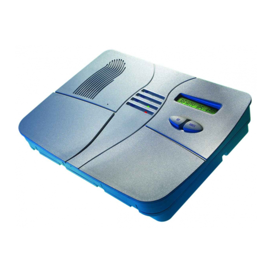
POWERMAX+
Fully Supervised Wireless Alarm Control System
TABLE OF CONTENTS
1. INTRODUCTION............................................................3
2. SPECIFICATIONS .........................................................3
2.1 General Data............................................................3
2.2 RF Section ...............................................................3
2.3 Electrical Data..........................................................3
2.4 Communication ........................................................4
2.5 Physical Properties ..................................................4
3. INSTALLATION ..............................................................4
3.1 Unpacking the Equipment.........................................4
3.2 Supplying Power to the Unit......................................4
3.3 System Planning and Programming .........................4
3.4 Mounting ..................................................................4
3.5 Wiring ........................................................................4
3.6 Connecting the AC Transformer ...............................7
3.7 Installing an Optional X-10 Siren ..............................7
3.8 Connecting PowerMax+ to a Computer....................7
3.9 Connecting PowerMax+ to GSM Modem .................7
4. PROGRAMMING ...........................................................7
4.1 INTRODUCTION...........................................................7
4.1.1 General Guidance..................................................7
4.1.2 Entering an Invalid Installer Code..........................8
4.1.3 Installer's Menu ......................................................8
4.1.4 Setting a New Installer Code .................................8
that has 2 Installer Codes ......................................8
4.2.1 General Guidance..................................................8
4.2.2 Enrolling Type ........................................................9
4.2.3 Enroll / Delete Wireless Devices ...........................9
4.2.4 Enroll / Delete Keyfob Transmitters .....................10
4.2.5 Enroll / Delete Wireless Commander ..................10
4.2.6 Enroll / Delete 2-Way Keypad..............................10
4.2.7 Enroll / Delete Wireless Siren..............................10
4.4 DEFINING CONTROL PANEL PARAMETERS.........11
4.4.1 Preliminary Guidance...........................................11
4.4.3 Exit Delay .............................................................11
4.4.4 Bell Time ..............................................................11
4.4.5 Abort Time ...........................................................11
4.4.6 Alarm Cancel ......................................................11
4.4.7 Quick Arm ............................................................12
4.4.8 Bypass .................................................................12
4.4.9 Exit Mode .............................................................12
4.4.10 Piezo Beeps.......................................................12
4.4.11 Trouble Beeps....................................................12
4.4.12 Panic Alarm........................................................12
4.4.13 Swinger Stop......................................................12
4.4.14 Cross Zoning......................................................12
4.4.15 Supervision ........................................................12
4.4.16 NOT READY......................................................12
4.4.17 AUX Button ........................................................12
4.4.18 Jam Detect.........................................................12
4.4.19 Latchkey ............................................................12
4.4.20 "Not Active" .......................................................13
4.4.21 Back Light ..........................................................13
4.4.22 Duress ...............................................................13
4.4.23 Piezo Siren ........................................................13
4.4.24 Reset Option......................................................13
4.4.25 Tamper Option...................................................13
4.4.26 Siren on Line......................................................13
4.4.27 Memory Prompt .................................................13
4.4.28 Disarm Option....................................................13
4.4.29 Bell/Rep. Option.................................................13
4.4.30 Low-Bat ACK .....................................................13
4.4.31 Screen Saver .....................................................13
4.4.32 Confirm Alarm....................................................13
4.4.33 AC Fail Rep .......................................................13
4.4.35 User Permission ................................................13
4.5 DEFINING COMMUNICATION PARAMETERS ........15
4.5.1 Autotest Time.......................................................15
4.5.2 Autotest Cycle......................................................15
4.5.3 Area Code............................................................15
4.5.4 Out Access Code.................................................15
4.5.5 First Central Station Telephone...........................15
4.5.6 First Account No. .................................................15
4.5.7 Second Central Station Telephone .....................15
4.5.8 Second Account No.............................................15
4.5.9 Report Format......................................................15
4.5.10 4/2 Pulse Rate ...................................................15
4.5.11 Reporting to Central Stations ............................15
4.5.12 Report CNF Alarm .............................................15
4.5.13 Send 2WV Code................................................15
4.5.14 Two-Way Voice Central Stations.......................15
4.5.15 Ring Back Time .................................................17
4.5.16 Dialing Attempts.................................................17
4.5.17 Set Private Telephone No. ................................17
4.5.18 Two-Way Voice - Private Phones......................17
4.5.19 Private Telephone Dialing Attempts ..................17
4.5.20 Reporting to Private Telephones.......................17
4.5.21 Telephone Acknowledge ...................................17
4.5.22 Pager Telephone Number .................................17
4.5.23 Pager's PIN No. .................................................17
4.5.24 Reporting to a Pager .........................................17
4.5.25 Recent Closure ..................................................17
4.5.26 Remote Access .................................................17
4.5.27 Master Downloader Code..................................17
4.5.28 Installer Downloader Code ................................17
4.5.30 Zone Restore .....................................................17
Installer Guide
1
Advertisement
Table of Contents

Related Manuals for Visonic POWERMAX+


Summary of Contents for Visonic POWERMAX+
-
Page 1: Table Of Contents
POWERMAX+ Installer Guide Fully Supervised Wireless Alarm Control System TABLE OF CONTENTS 4.4.15 Supervision ............12 1. INTRODUCTION............3 4.4.16 NOT READY............12 2. SPECIFICATIONS ............3 4.4.17 AUX Button ............12 2.1 General Data............3 4.4.18 Jam Detect............12 2.2 RF Section ...............3 4.4.19 Latchkey ............12 2.3 Electrical Data............3 4.4.20 “Not Active”... - Page 2 4.5.31 Upload Option ............17 5.2 Diagnostic Test............23 4.5.32 Dialing Method ...........17 5.3 Keyfob Transmitter Test ........23 4.5.33 Line Failure Report ..........17 5.4 Appliance ON/OFF Test ........23 4.5.34 UL/DL Telephone Number.........18 5.5 Emergency Transmitter Test .........24 4.5.35 System Inactive Report........18 6. MAINTENANCE............24 4.5.36 Ring Back Code ..........18 6.1 Dismounting the Control Panel......24 4.5.37 Receiver Number..........18...
-
Page 3: Introduction
1. INTRODUCTION • The PowerMax+ is a user and installer-friendly, 30-zone Diagnostic test provides visual and audible indication of fully-supervised wireless control system. The system is the signal level of each detector. • designed to function in a way that appeals to the user but Remote control and status verification from distant also offers features that make installers’... -
Page 4: Communication
Current Drain: Approx. 65 mA standby, 800 mA at full (Provides backup for up to 24 hours): load and in alarm. Rechargeable NiMH battery pack 7.2V installations 2100 mAh p/n GP211ATH6XML, or 7.2V Site External Siren Current (EXT): 550* mA max @ 10.5 2200mAh GP220AAH6YMX, VDC when powered by AC &... - Page 5 BRACKET REMOVAL Remove Pull down Remove bracket the bracket locking until click bracket screw is heard BRACKET MOUNTING MOUNTING THE UNIT ON THE BRACKET MOUNTING SURFACE Screw holes Screw holes NOTE Mark and drill 4 holes in mounting Verify that there is 3 cm Locate the panel on the bracket surface.
- Page 6 CONNECT WIRED DETECTORS AS FOLLOWS: Detector with Detector without Note Tamper switch Tamper switch Regarding zones 29 & 30, the Control TAMP Alarm Alarm Panel “sees” a specific resistance N.C. N.C. Power N.C. Power according to the event, as follows: Normal (no alarm &...
-
Page 7: Connecting The Ac Transformer
f. A minimum spacing of 1/4 inch shall be maintained House Code: Set this selector to the letter that follows, by between the telephone wiring and the low voltage alphabetical order, the letter that you programmed as a wiring (zones, bell circuit, etc). Do not route the LINE house code for the protected premises. -
Page 8: Entering An Invalid Installer Code
4.1.4 Setting a New Installer Code 4.1.2 Entering an Invalid Installer Code To set an installer code, perform the actions that are If you enter an invalid installer code 5 times, the keypad presented in figure 4.1b. When you are instructed to enter will be automatically disabled for 30 seconds. -
Page 9: Enrolling Type
NEXT NEXT ENROLLING TYPE NEXT ENROLL WL DEVICE ENROLL KEYFOB normal enroll SET SENSITIV. Keyfob No: - by tamper higher sensitivity [Keyfob No.] (****) (e.g. 5) (**) lower sensitivity Select by Keyfob No: 5 Keyfob No: 5 NEXT TRANSMIT NOW <OFF>... -
Page 10: Enroll/Delete Keyfob Transmitters
4.2.6 Enroll/Delete 2-Way Keypad 4.2.4 Enroll/Delete Keyfob Transmitters (Not evaluated by UL). (Applicable for PowerMax+ revision B and above). Keyfob transmitters are multi-button wireless CodeSecure™ The 2-way keypad, type MKP-150, enables the user to transmitters. Eight system users use them for better, remotely control the system and also to receive data from quicker and safer control over various system functions. -
Page 11: Defining Control Panel Parameters
Table 1 - DEFAULT AND PROGRAMMED ZONE DEFINITIONS Zone Zone Type Zone Name Chime (melody Default Programmed Default Programmed Zone Name or Off) (*) Delay 1 Front Door Delay 1 Garage Delay 2 Garage Door Perimeter Back Door Perimeter Child Room Interior Office Interior... -
Page 12: Quick Arm
4.4.7 Quick Arm 4.4.14 Cross Zoning (fig. 4.4, location 07) (fig. 4.4, location 14) Here you determine whether the user will be allowed to Do not use in UL installations. perform quick arming or not. Once quick arming is Here you determine whether cross zoning will be active or permitted, the control panel does not request a user code inactive. -
Page 13: Not Active
4.4.20 “Not Active” 4.4.28 Disarm Option (fig. 4.4, location 20) (fig. 4.4, location 28) Here you determine when it is possible to disarm the system: (Not evaluated by UL). A. Any time. Here you determine the time limit for reception of signals B. - Page 14 READY 00:00 NEXT NEXT NEXT NEXT 01: ENTRY DELAY 1 02: ENTRY DELAY 2 03: EXIT DELAY 04: BELL TIME NEXT NORMAL MODE entry dly1 00 s entry dly2 00 s exit delay 30 s bell time 1 m NEXT bell time 3 m entry dly1 15 s entry dly2 15 s...
-
Page 15: Defining Communication Parameters
4.5 DEFINING COMMUNICATION PARAMETERS Preliminary Guidance 4.5.9 Report Format (fig. 4.5, location 09) This mode allows adapt telephone Here you select the reporting format used by the control panel communication parameters to the local requirements. to report events to central stations (see note in figure 4.5). Note: For all UL-certified systems, it is up to the The options are: Contact-ID... - Page 16 READY 00:00 NEXT NEXT NEXT NEXT 01: AUTOTEST TIME 02:AUTOTST CYCLE 03:AREA CODE 04: OUT ACCESS No NEXT NORMAL MODE test every 1d NEXT Test time 12:00 P xxxx test every 5d USER SETTINGS (Enter tel. area (Enter ext. tel. line test every 7d (Enter test time) code, up to 4-digit)
-
Page 17: Ring Back Time
4.5.15 Ring Back Time message that the PowerMax+ sends to the pager to report (fig. 4.5, location 15) an event. It may include digits, pauses and special Here you determine the period during which the central ∗ characters ( or #). Call the paging company to find out station can establish 2-way voice communication with the what the pager’s PIN code should consist of. -
Page 18: Ul/Dl Telephone Number
4.5.34 UL/DL Tel. Number 4.5.36 Ring Back Code (fig. 4.5, loc. 34) (fig. 4.5, loc. 36) Here you enter the telephone number (up to 16 digits) of Here you enter a 6-digit code that will be used by the the UL/DL server. central station to activate ring back to the system. -
Page 19: Gsm Line Failure Reporting
4.6.4 GSM Line Failure Reporting 4.6.5 GSM Line Purpose Define whether the GSM unit will serve as a backup for the Here you determine whether GSM network failure will be regular telephone line, as a primary communication reported after 2 min., after 5 minutes, after 15 min., or after channel or as the only telephone channel or for sending 30 minutes. - Page 20 (First display is READY NEXT NEXT NEXT NEXT DEFINE PGM DEFINE INT/STRB X-10 GENERAL DEF X-10 UNIT DEFINE or NOT READY) READY 00:00 internal siren SET HOUSE CODE NEXT strobe See detail “A” NORMAL MODE (next page) house code =A NEXT house code =B USER SETTINGS...
-
Page 21: Recording Speech
The currently saved option is displayed with a dark box at the right side. To review the options, repeatedly click NEXT button until the desired option is displayed, then click OK (a dark box will be displayed at the right side). For zone name list, refer to paragraph 4.3 (DEFINE ZONE TYPES). -
Page 22: User Functions
(see figure 4.1a) 10. DIAGNOSTICS NEXT NEXT NEXT WL SENSORS TEST WL SIRENS TEST WL KEYPADS TEST DIAG. TESTING (Perform walk test) Example WAIT WAIT BATHROOM of test CPU=STRONG CPU=STRONG result Z19 STRONG display NEXT NEXT DIAG. TESTING Example FRONT DOOR PLEASE WAIT... -
Page 23: Testing Procedures
READY 00:00 NEXT If UL/DL server If UL/DL server NORMAL MODE tel. # is already tel. # was not NEXT defined (see defined before USER SETTINGS par. 4.5.34) (see par. 4.5.34) NEXT INSTALLER MODE Displayed for half Displayed during a minute approx. ENTER CODE COMMUNICATING TEL # NOT DEFINED... -
Page 24: Emergency Transmitter Test
The easiest way for test timed activation is to select the Go over the table in Appendix B column by column. If, for instance, the “BY ARM AWAY” column has “X”s marked in ninth item in the installer’s menu (”10. USER SETTINGS”) the rows pertaining to units 1, 5 and 15 - then arm AWAY and set the system clock a few minutes before the relevant the system and verify that the appliances controlled by... -
Page 25: Appendix A. Detector Deployment And Transmitter Assignments
APPENDIX A. Detector Deployment & Transmitter Assignments A1. Detector Deployment Plan Zone Zone Type Sensor Location or Transmitter Assignment Chime Controls PGM Controls (in non-alarm or emergency zones) (Yes / No) (X = YES) X-10 Unit No. 29 (*) 30 (*) Zone Types: 1 = Interior follower 2 = Perimeter 3 = Perimeter follower... -
Page 26: A3. Emergency Transmitter List
A3. Emergency Transmitter List Tx # Transmitter Type Enrolled to Zone Name of holder A4. Non-Alarm Transmitter List Tx # Transmitter Type Enrolled to Zone Name of holder Assignment APPENDIX B. X-10 Unit and PGM Output Assignments Unit Controlled ON by Timer ON by Zone No. -
Page 27: Appendix C. Event Codes
APPENDIX C. Event Codes Note: For USA only, ID and SIA report all keyfob panics from zone 0 - not from the keyfob user number. Contact ID Event Codes SIA Event Codes Code Definition Code Definition Code Definition Code Definition Emergency Telco fault AC Restore... -
Page 28: Appendix D. Programmable Zone Types
Panic / 24 Hours - 8 users Note: For USA only, 4/2 report all keyfob panics as event 21 - not depending on the user keyfob number!!! User No. Panic CP Duress digit digit Arm HOME and AWAY (Closing) User No. Cancel alarm Recent Close digit... -
Page 29: Appendix E. Powermax+ Compatible Devices
D4. Flood Zone For remote control of electrical devices, you can define the desired number of non-alarm zones and enroll a portable A flood zone is permanently active (a flood alarm is transmitter or a wireless device (detector) to this type of triggered regardless of whether the system is armed or zone. -
Page 30: E2 Powermax+ Compatible Transmitters
C. MCT-134 / 104* C. MCT-100 Wireless Adapter for Wired Detectors (N.A. in North America) (not UL-Listed) MCT-100 is a PowerCode 4-button hand-held units. MCT- device used mainly as a wireless adapter for 2 regular magnetic switches installed on 134 (CodeSecure) can replace 2 windows in the same room. -
Page 31: Fcc Statements
Supplier Declaration of Conformity (SdoC) Visonic, located at 30, 24 Habarzel street, Tel Aviv 69710, Israel, hereby certifies that the Wireless Alarm Control Panel model “PowerMax+”, bearing the labeling identification number US:VSOAL03BPOWERMAX+ complies with the Federal Communication Commission’s (“FCC”) Rules and Regulations 47 CFR Part 68, and the Administrative Council on Terminal... -
Page 32: Declaration Of Conformity
Products. VISONIC LTD. (ISRAEL): P.O.B 22020 TEL-AVIV 61220 ISRAEL. PHONE: (972-3) 645-6789, FAX: (972-3) 645-6788 VISONIC INC. (U.S.A.): 65 WEST DUDLEY TOWN ROAD, BLOOMFIELD CT. 06002-1376. PHONE: (860) 243-0833, (800) 223-0020. FAX: (860) 242-8094 VISONIC LTD. (UK): FRASER ROAD, PRIORY BUSINESS PARK, BEDFORD MK44 3WH.
Need help?
Do you have a question about the POWERMAX+ and is the answer not in the manual?
Questions and answers