Visonic POWERMAX+ Installation Instructions Manual
Fully supervised wireless alarm
Hide thumbs
Also See for POWERMAX+:
- User manual (38 pages) ,
- Installer's manual (32 pages) ,
- Programming manual (24 pages)
Table of Contents
Advertisement
Quick Links
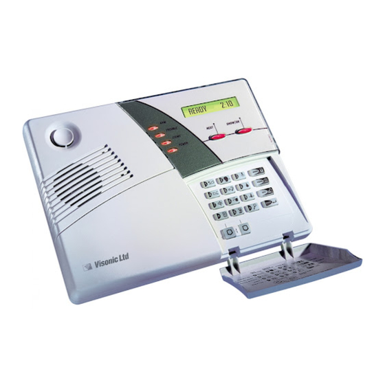
POWERMAX+
Fully Supervised Wireless Alarm Control System
TABLE OF CONTENTS
1. INTRODUCTION ........................................................ 2
2. SPECIFICATIONS ..................................................... 2
2.1 General Data....................................................... 2
2.2 RF Section .......................................................... 2
2.3 Electrical Data ..................................................... 2
2.4 Communication ................................................... 3
2.5 Physical Properties ............................................. 3
3. INSTALLATION.......................................................... 3
3.1 Unpacking the Equipment .................................... 3
3.2 Supplying Power to the Unit................................. 3
3.3 Programming........................................................ 3
3.4 Mounting ............................................................. 3
3.5 Wiring ................................................................... 3
3.6 Connecting the AC Transformer .......................... 6
3.7 PowerMax+ Compatible Detectors....................... 6
3.8 PowerMax+ Compatible Transmitters .................. 6
3.9 PowerMax+ Compatible WL Siren ....................... 7
3.10 Installing an Optional X-10 Siren.......................... 7
3.11 Connecting PowerMax+ to a Computer ............... 7
3.12 Connecting PowerMax+ to GSM Modem............. 7
MESSAGE TO THE INSTALLER
The PowerMax+ control panel is supplied with 3 instruction manuals:
Installation Instructions (this manual - for your exclusive use)
Programming Guide (for your exclusive use)
User's Guide (for your use during installation only. Must be handed over to the master user after testing the system).
Appendices A and B of the installation instructions will help you prepare an installation plan. Please take time to fill out the
forms - your job will become much easier and confusion will be prevented. Filling out the forms will also help you create a
list of detectors and transmitters that must be obtained for the particular application. Compatible detectors and transmitters
are listed and described briefly in Paragraphs 3.7 and 3.8 of this manual.
Remember - it is advisable to power up the control panel temporarily after unpacking and program it on the work bench, in
accordance with the installation plan. Paragraph 3.3 of this manual refers you to the programming guide.
The programming flow charts in the programming guide show all options available for each parameter. Factory defaults are
marked with a dark box to their right, and other options (that can be selected instead) are marked by clear boxes. This
method allows you to put a checkmark in the appropriate clear box whenever you deviate from the factory defaults.
Although setting the correct time and date is one of the user tasks, we recommend that you set the time and date in the
course of programming. Access to the "User Settings" for the installer is possible through item 10 on the installer's menu or
through the user menu (see User's manual section 7).
After programming, proceed to install the system as detailed in the Installation Instructions, from paragraph 3.4 onward.
WARNING! Zone type "emergency" can not be used for medical applications in UL-listed systems.
The installer should verify line seizure. Be aware of other phone line services such as DSL.
DE5465
Installation Instructions
4. TESTING PROCEDURES .......................................... 7
4.1 Preparations ........................................................ 7
4.2 Diagnostic Test.................................................... 7
4.3 Keyfob Transmitter Test ...................................... 7
4.4 Appliance ON/OFF Test ...................................... 8
4.5 Emergency Transmitter Test ............................... 8
5. MAINTENANCE.......................................................... 8
5.1 Dismounting the Control Panel............................ 8
5.2 Replacing the Backup Battery ............................. 8
5.3 Fuse Replacement .............................................. 8
5.4 Replacing/Relocating Detectors .......................... 8
TRANSMITTER ASSIGNMENTS ............................... 9
A.1 Detector Deployment Plan .................................. 9
A.2 Keyfob Transmitter List ....................................... 9
A.3 Emergency Transmitter List .............................. 10
A.4 Non-Alarm Transmitter List ............................... 10
ASSIGNMENTS ........................................................ 10
FCC STATEMENTS ....................................................... 11
1
Advertisement
Table of Contents

Subscribe to Our Youtube Channel
Related Manuals for Visonic POWERMAX+


Summary of Contents for Visonic POWERMAX+
-
Page 1: Table Of Contents
POWERMAX+ Installation Instructions Fully Supervised Wireless Alarm Control System TABLE OF CONTENTS 1. INTRODUCTION ............2 4. TESTING PROCEDURES .......... 7 2. SPECIFICATIONS ............. 2 4.1 Preparations ............7 2.1 General Data............2 4.2 Diagnostic Test............ 7 2.2 RF Section ............2 4.3 Keyfob Transmitter Test ........ -
Page 2: Introduction
1. INTRODUCTION • The PowerMax+ is a user and installer-friendly, 30-zone Diagnostic test provides visual and audible indication of fully-supervised wireless control system. The system is the signal level of each detector. • designed to function in a way that appeals to the user but Remote control and status verification from distant also offers features that make installers’... -
Page 3: Communication
650 to 1800 mAh. Storage Temp. Range: -4°F to 140°F (-20°C to 60°C) Note: To use a non-Visonic battery pack, its battery snap Humidity: 85% relative humidity, @ 30°C (86°F) should have proper polarity! Size: 9-13/16 x 7-1/2 x 1-3/4 in. (250 x 190 x 44 mm) Battery Test: Once every 10 seconds. - Page 4 Open Release battery Remove battery Remove bracket keypad area cover area cover locking screw cover BATTERY AREA COVER SLOT Screw holes Special plastic washer Screw holes Special plastic Mark and drill 4 holes in washer mounting surface. Insert wall anchors and fasten the bracket to the mounting surface with 4 screws Push the bracket as shown...
- Page 5 CONNECT WIRED DETECTORS AS FOLLOWS: Detector with Detector without Note Tamper switch Tamper switch Regarding zones 29 & 30, the TAMP Alarm Alarm PowrMax+ “sees” a specific resistance N.C. N.C. Power N.C. Power according to the event, as follows: Normal (no alarm & no tamper): 2.2 k Ω Alarm event: 4.4 k Ω...
-
Page 6: Connecting The Ac Transformer
C. MCT-100 Wireless Adapter for Wired Detectors 3.6 Connecting the AC Transformer (not UL-Listed) MCT-100 (fig. 8) is a CAUTION! Do not plug the transformer into the AC PowerCode device used mainly as a outlet before completing all other wiring. wireless adapter for 2 regular magnetic A. -
Page 7: Powermax+ Compatible Wl Siren
via the built-in electrical wiring of the protected site. This C. MCT-134 / 104* (Fig. 13): siren can replace the regular external siren or complement it (N.A. in North America) without laying out additional wires. Of course, such a siren 4-button hand-held units. -
Page 8: Appliance On/Off Test
Press the keyfob unit’s DISARM ( ) key. The ARM indicator Continue in the same manner in the following columns, should extinguish, the announcement “Disarm, ready to arm" always creating the state or event that will activate the should be heard and the display should revert to: relevant units. -
Page 9: Appendix A. Detector Deployment And Transmitter Assignments
APPENDIX A. Detector Deployment & Transmitter Assignments A1. Detector Deployment Plan Zone Zone Type Sensor Location or Transmitter Assignment Chime Controls PGM Controls (in non-alarm or emergency zones) (Yes / No) (X = YES) X-10 Unit No. 29 (*) 30 (*) Zone Types: 1 = Interior follower 2 = Perimeter 3 = Perimeter follower... -
Page 10: Emergency Transmitter List
A3. Emergency Transmitter List Tx # Transmitter Type Enrolled to Zone Name of holder A4. Non-Alarm Transmitter List Tx # Transmitter Type Enrolled to Zone Name of holder Assignment APPENDIX B. X-10 Unit and PGM Output Assignments Unit Controlled ON by Timer ON by Zone No. -
Page 11: Fcc Statements
Supplier Declaration of Conformity (SdoC) Visonic, located at 30, 24 Habarzel street, Tel Aviv 69710, Israel, hereby certifies that the Wireless Alarm Control Panel model “PowerMax+”, bearing the labeling identification number US:VSOAL03BPOWERMAX+ complies with the Federal Communication Commission’s (“FCC”) Rules and Regulations 47 CFR Part 68, and the Administrative Council on Terminal... - Page 12 Product due to products, accessories, or attachments of others, including batteries, used in conjunction with the Products. VISONIC LTD. (ISRAEL): P.O.B 22020 TEL-AVIV 61220 ISRAEL. PHONE: (972-3) 645-6789, FAX: (972-3) 645-6788 VISONIC INC. (U.S.A.): 10 NORTHWOOD DRIVE, BLOOMFIELD CT.
Need help?
Do you have a question about the POWERMAX+ and is the answer not in the manual?
Questions and answers