Table of Contents
Advertisement
Quick Links
Chapter 2
Installation
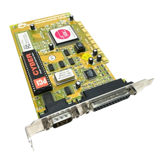
This chapter will guide you through the installation of your
Cyber I/O PCI. There are no jumpers or switches to set for this
PCI Plug-n-Play board.
2-1 Installing the Cyber I/O PCI
Proceed with the following instructions to install the board in
your computer. General installation instructions are given
since the design of computer cases varies. Refer to your
computer's reference manual whenever in doubt.
Note: Leave the Cyber I/O PCI board in its
static-resistant bag until you are ready to install it.
1. Turn OFF the power to your computer and any other
connected peripheral devices. Follow the precautions for
static electricity discharge.
CAUTION: STATIC ELECTRICITY DISCHARGE
may permanently damage your system. In order to
avoid possible static electricity discharge during
installation procedures, please follow the guidelines
below:
• Discharge any static electricity build up in your body by
touching a large grounded metal surface such as the
computer case (if plugged in), a metal window frame,
refrigerator, or water tap for a few seconds.
• During installation procedures, avoid any contact with
internal parts. Handle cards only by their edges.
CAUTION: Disconnect the AC power source
before removing the cover.
Installation
2-1
Advertisement
Table of Contents

Related Manuals for SIIG Cyber I/O PCI


Summary of Contents for SIIG Cyber I/O PCI
-
Page 1: Chapter 2 Installation
Chapter 2 Installation This chapter will guide you through the installation of your Cyber I/O PCI. There are no jumpers or switches to set for this PCI Plug-n-Play board. 2-1 Installing the Cyber I/O PCI Proceed with the following instructions to install the board in your computer. - Page 2 Cyber I/O PCI after it’s installed. Fig. 2-1. Remove the Slot Bracket 6. To install the Cyber I/O PCI, carefully align the board’s bus connector with the selected expansion slot on the motherboard. Push the board down firmly, but gently,...
- Page 3 NOTE: Hold the card by its external edges only. Try to avoid touching the components, connectors or pins. Fig. 2-2. Install the Cyber I/O PCI 7. Replace the slot bracket's holding screw to secure the board to the rear slot panel.
- Page 4 Perform the following steps to install the drivers for Windows 95/98: When you first turn on your computer after installing the Cyber I/O PCI card, Windows will notify you of “New Hardware Found”. From the choices listed on the screen, select: “•...
- Page 5 From the desktop, double-click on My Computer, then 3 1/2 Floppy (A:) and NT subdirectory. 4. Double-click on the setup icon. When the program opens to the “SIIG Cyber PCI Welcome” window, click on Next to continue. From the “Choose Destination Location” window, click Next to install the driver files in the default folder.
- Page 6 You can run either utilities from the diskette, or copy them to a subdirectory on your hard drive. CB10xpc.exe The default baud rate for your Cyber I/O PCI's serial port is 115.2Kbps. And the I/O port address and mode setting for the parallel port are automatically assigned during the system's startup.
- Page 7 CB10xsu.exe Speed Change The default baud rate for your Cyber I/O PCI's serial port is 115.2Kbps. If you connect a higher speed device, you may change the baud rate to support up to 460Kbps.
- Page 8 Cyber I/O PCI User's Manual Mode Change Your Cyber I/O PCI supports EPP/ECP, ECP, EPP, and BPP/SPP modes. The default mode setting is EPP/ECP. You can change the mode by running cb10xsu.exe. 1. Go to My Computer in Windows 95 and click on the subdirectory where the DOS utility files are stored.
Need help?
Do you have a question about the Cyber I/O PCI and is the answer not in the manual?
Questions and answers