Table of Contents
Advertisement
Quick Links
Advertisement
Table of Contents

Related Manuals for SIIG CE-H23J11-S1


Summary of Contents for SIIG CE-H23J11-S1
- Page 1 HDMI 2.0 4-Display Video Wall Processor User Manual 04-1141A P/N: CE-H23J11-S1...
-
Page 2: Safety And Notice
Safety and Notice The HDMI 2.0 4-Display Video Wall Processor has been tested for conformance to safety regulations and requirements, and has been certified for international use. However, like all electronic equipment, the HDMI 2.0 4-Display Video Wall Processor should be used with care. -
Page 3: Package Contents
Features • DisplayPort 1.2a & HDMI 2.0a compliant • HDCP compliant • Four HDMI outputs from 640x480 to 1920x1200 • Supports HDMI and DisplayPort input from 640x480 to 4K2K@60 (YUV 4:4:4), interlaced or progressive • Image parameters and layouts are automatically saved in flash memory of the device and can be recalled for later use •... -
Page 4: Specifications
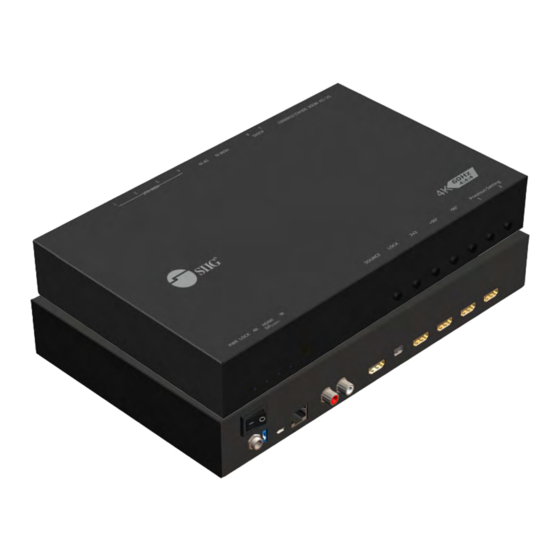
SPECIFICATIONS Technical Role of usage Video Wall Processor HDCP compliance Input – Single link 600MHz [18Gbps] Video bandwidth Output –Single-link 225MHz [6.75Gbps] Input - 4K2K@60 (4:2:2 8bits) / 4K2K@60 (4:4:4 8bits) Video support Output – 1920x1080@60 / 1920x1200@60 Video Format Support HDMI / DisplayPort Audio support PCM 2ch... - Page 5 Layout Front Panel 1. LED indicator: PWR – Power indicator LED LOCK – When device status is locked, it will shine 4K – If source resolution is 4K, the LED indicator will shine Source – When source from HDMI, the LED indicator will shine Source from DisplayPort, the LED indicator will blink 2.
-
Page 6: Hdmi Input
Rear Panel 4. Power Switch: Power ON/OFF switch 5. +12V DC: 12V DC power jack 6. Dip Switch: On for normal use Off for F/W upgrade 7. USB virtual COM 8. Ethernet: Ethernet control port 9. Stereo audio output – L 10. -
Page 7: Operation Approach
Application Operation Approach Method A: Software Operation System Requirement and Precautions Whenever power off HDMI 2.0 4-Display Video Wall Processor, please stay unpowered at least 5 to 10 seconds to allow power capacitors to discharge. The HDMI 2.0 4-Display Video Wall Processor provides software control program which runs under Microsoft Windows 7, 8.1, 10 through the interface of USB virtual com control. - Page 8 Start the software control program Executing the control software, the following dialog will pop up. It has two ways to control the HDMI 2.0 4-Display Video Wall Processor device (under Microsoft Windows 7, please run as administrator). USB Connection: Use USB to connect the port on device and computer.
- Page 9 Connection Status: Show the connect information and status. If you use USB control Mode to connect device, the graph is . For IP control, the graph of Ethernet is Quick Selection: *Quick Selection function is not available when the input resolution is 4K2K@60Hz In this part, you can set up the screen resolution, screen coordinate and split screen.
- Page 10 Output Selection and Resolution: (1)Step 1: check input resolution and choose output resolution Set the output resolution. You can choose the design display icon to select the output port and setup resolution. When setting the different resolution, the coordinate of output will also be changed. In this part, you also can select input source (HDMI or DisplayPort) or lock/unlock the device.
- Page 11 Step 2-1: quick selection If you choose the Quick Selection mode in step 2, this window will automatically pop up. In this mode, you can select default screen split and rotate screen (rotate screen only at 1080p resolution). 3x1: This mode will divide the screen into 3 parts and rotate the figure.
- Page 12 Step 2-3: custom define In Custom define mode, you can define how to cut in both directions and the part you want to show on output TV. If you want to know or estimate which parts you select, you can click the Grid button to show grid on the graph.
- Page 13 EDID (Extended Display Identification Data) Advanced Setting...
- Page 14 4K2K Setting When input is 4K2K@60Hz Resolution, the output display will be forced to 2x2 layout (other layout cannot set) and only can set up the output position. We also provide 8 preset spaces to save the frequently used scenarios into the device. Cloud setting-Association Code Clicking “ASSC“...
- Page 15 IP Configure You can also use the Ethernet to control the software program. First, you should click the “IP CONFIGURE“ button to setup network. Next, read the Ethernet setting from your device and manually set to the device or click the DHCP button to automatically get the IP address. After the step of IP configuration, please restart the machine.
- Page 16 Method B: Firmware Update through mini-USB Port Please ensure the file of new firmware file is in the root directory of USB Flash Drive. The file name should be “firmware.bin”. Use mini-USB to female USB type A cable to connect the USB interface of device and USB Flash Drive.
- Page 17 Add Device to intriCloud Firstly, please make sure the device is connected to the Ethernet. Then please execute the software from the device to get the association code (Note: the status of software is connected). Access intriCloud ( www.intri.cloud)or download IntriCloud APP,and then log in your account on the right top corner.
- Page 18 Enter the Installer Email for online support in the future, and the Association Code for pairing with your device. After adding the device, the list of device related to your account will show on the right top corner. You can click the button to switch device for control.
-
Page 19: Edid Learning
EDID Learning The EDID learning function is only necessary whenever you encoun- ter any display on the HDMI output port that cannot play audio and video properly. Because the HDMI sources and displays may have various level of capability in playing audio and video, the general principle is that the source will output the lowest standards in terms of audio format and video resolutions to be commonly acceptable among all HDMI displays. - Page 20 Support For more info or tech support http://www.siig.com/support Sep, 2018 Copyright © 2018 by SIIG, Inc. All rights reserved.
Need help?
Do you have a question about the CE-H23J11-S1 and is the answer not in the manual?
Questions and answers