
Related Manuals for YOKOGAWA Dpharp vigilantplant EJA Series


Summary of Contents for YOKOGAWA Dpharp vigilantplant EJA Series
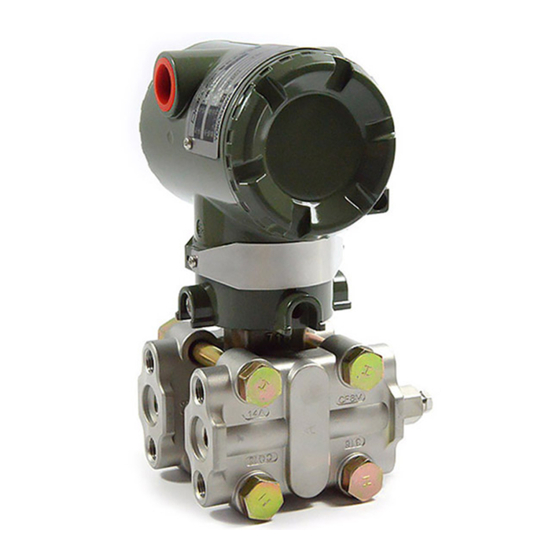
- Page 1 User’s Manual Model EJA Series HART Protocol IM 01C22T01-01E IM 01C22T01-01E 7th Edition Yokogawa Electric Corporation...
-
Page 2: Table Of Contents
(1) Identify Problems with HART Communicator ......2-19 (2) Checking with Integral Indicator ..........2-20 PARAMETER LISTS ..................3-1 REVISION RECORD FD No. IM 01C22T01-01E 7th Edition: Jan. 2008(KP) All Rights Reserved, Copyright © 1995, Yokogawa Electric Corporation IM 01C22T01-01E... -
Page 3: Preliminary
3) Call "Simulation" and press [ ] . Figure 1. Relationship between Individual Manuals and 4) Select "YOKOGAWA" from manufacturers HART Manual Contents list by pressing [ ] and press [ ] . 5) Select the model name of the instrument(i.e. -
Page 4: Zero Point Adjustment
1. ZERO POINT ADJUSTMENT ZERO POINT ADJUSTMENT Using the HART Communicator After operating preparation is completed, adjust the zero point. The zero point adjustment can be made Zero point can be adjusted by simple key operation of using either of the following two methods. the HART Communicator. -
Page 5: Using The Hart Communicator
1. ZERO POINT ADJUSTMENT 1.1.1 Using the HART Communicator 1. Device setup 2. Diag/Service (1) Zeroing — Zero trim 3. Calibration 3. Sensor trim NOTE 2. Lower Sensor Trim Zero trim carries out the zero adjustment and sets the input values at present, equal to 0 EJA: O. -
Page 6: Auto Lrv (Change Low Range Value)
1. ZERO POINT ADJUSTMENT 1.2 Auto LRV (Change Low 1.2.2 Setting the Range Using the Range- setting Switch Range Value) With actual pressure(s) being applied to the transmitter, 1.2.1 Using Model 275 — Apply Values the range-setting switch (push-button) attached to the integral indicator plate and the external zero-adjust- Display the Apply Values display, and adjust the zero ment screw allow users to change the lower- and... - Page 7 1. ZERO POINT ADJUSTMENT IMPORTANT 1. Do not turn off the power to the transmitter immediately after completion of the change in the LRV (and/or URV) setting(s). Note that powering off within thirty seconds after setting will ca use a return to the previous settings. 2.
-
Page 8: Hart Communicator Operation
2. HART COMMUNICATOR OPERATION HART COMMUNICATOR OPERATION 2.1 Conditions of Communica- 2.1.2 Communication Line Requirements tion Line Specifications for Communication Line: Supply voltage(general use type); 16.4 to 42 V DC 2.1.1 Interconnection Between DPharp Load resistance; 250 to 600 W (Including cable and HART Communicator resistance) The HART Communicator can interface with the... -
Page 9: Basic Operation Of The Hart Communicator (Model 275)
Function keys Functions of the keys are indicated on the display. Pressing (HOME) when the display is as shown changes the display to “Online” EJA:YOKOGAWA menu. (See 2.2.2 “Display”.) Process variables 1 Pres 0.00 mmH2O 2 % rnge 0.00 % 3 A01 Out 4.000mA... -
Page 10: Display
Tag (8 Characters) <a> current menu device, or mark because of a current menu data to send comunication error EJA :YOKOGAWA PGUP PGDN Online answer to move up one move down one answer to <b> 1 Device setup... -
Page 11: Entering, Setting, And Sending Data
4 Device information transmission is complete. 5 Xfer fncth HELP SAVE HOME ENTER F0208.EPS Example: To change from Tag YOKOGAWA to FIC-1A. Call up the Tag setting display. 1. Device setup 3. Basic setup 1. Tag EJA:YOKOGAWA YOKOGAWA YOKOGAWA HELP ENTER F0206.EPS... -
Page 12: Parameters
2. HART COMMUNICATOR OPERATION 2.3 Parameters NOTE 2.3.1 Parameter Usage and Selection Do not turn off the transmitter as soon as HART Communicator settings (sending) have been Before describing the procedure for setting parameters, made. If the transmitter is turned of less than 30 we present the following table showing how the seconds after parameters have been set, the set prameters are used and in what case. -
Page 13: Menu Tree
2. HART COMMUNICATOR OPERATION 2.3.2 Menu Tree 1 PROCESS 1 Pressure Hot Key 1 Keypad Input 1 LRV VARIABLES 2 Percent Range 2 URV 3 Analog Output 3 Unit 4 Sensor Temperature 4 LSL 5 Static Pressure 5 USL 6 Engineering Unit 6 Min Span 7 Engineering Display 2 Wrt protect menu... -
Page 14: Setting Parameters
(3) Range Change T0202.EPS Ranges are factory-set as specified by the customer. To rerange, change the settings as follows: Example: To change from Tag YOKOGAWA to FIC-1A. Call up the Tag setting display. (a) Keypad — LRV, URV 1. Device setup... -
Page 15: Output Mode (Linear/Sq Root)
2. HART COMMUNICATOR OPERATION NOTE EJA: It is possible to set LRV URV. This setting Current applied process value: 500.01 mmH2O reverses the 4 to 20 mA output signal. (ENTER) 1 Set as 4mA value 2 Read new value The LRV to be changed is 500.01 Conditions: 3 Leave as found HELP... -
Page 16: Damping Time Constants
2. HART COMMUNICATOR OPERATION (5) Damping Time Constants (6) Output Signal Low Cut Mode Setup The damping constant is set to 2.0 seconds at the Low cut can be used on the output signal to stabilize factory. When changing the damping constant, proceed the output near the zero point. -
Page 17: Bi-Directional Flow Measurement
2. HART COMMUNICATOR OPERATION (7) Bi-directional Flow Measurement (8) Integral Indicator Display Mode (a) Bi-dir mode enables selection of 50% output at an input of 0 mmH Example: Change from Linear to Sq root 1. Device setup Example: If measurement range is 0 to 3000mmH (LRV = 0 mmH O, URV = 3000 mmH 4. - Page 18 2. HART COMMUNICATOR OPERATION Example: Set an engineering unit M. % indication and input User-set engineering pressure indication unit display 1. Device setup Set for user-set Normal % User set engineering unit Input press User set & % 4. Detailed setup display.
-
Page 19: Unit For Displayed Temperature
2. HART COMMUNICATOR OPERATION (10) Unit for Displayed Temperature (12) Test Output When the instrument is shipped, the temperature units This feature can be used to output a fixed current from are set to C (Centigrade). Follow the procedure below 3.2 mA (–5%) to 21.6 mA (110%) for loop checks. -
Page 20: Sensor Trim
2. HART COMMUNICATOR OPERATION CAUTION EJA: Press OK when pressure is stable 1. Test output is held for approximately 10 (OK) minutes, and then released automatically Press OK (F4). HELP ABORT after the time has elapsed. Even if the HART Communicator power supply is turned off or ‘1 0 0 0’... -
Page 21: Trim Analog Output
2. HART COMMUNICATOR OPERATION (14) Trim Analog Output Fine output adjustment is carried out with D/A trim or EJA: Fld dev output 4.000 Scaled D/A trim. mA equal to reference meter? (ENTER) 1 Yes • D/A Trim 2 No Ammeter reading: 4.000 D/A trim is to be carried out if the calibration HELP ABORT ENTER... - Page 22 2. HART COMMUNICATOR OPERATION Example 2: To adjust using a voltmeter ‘1 . 0 1’ EJA: Enter meter value 1.000 (ENTER) EJA: Trim analog output 1 D/A trim HELP ABORT ENTER Voltmeter reading: 1.010 2 Scaled D/A trim Enter the reading of the voltmeter Select the Scaled D/A trim item.
-
Page 23: Burst Mode
2. HART COMMUNICATOR OPERATION (15) Burst Mode (16) Multidrop Mode The transmitter continuously sends the data stored in it “Multidropping” transmitters refers to the connection when the burst mode is set on. Either one of measured of several transmitters to a single communications pressure variable, % output value, or 4 to 20 mA transmission line. -
Page 24: External Switch Mode
2. HART COMMUNICATOR OPERATION (18) Software Write Protect Example: Communication when set in the multi-drop mode EJA configured data is saved by the write protect function. Write protect status is set to YES when 8 alphanumerics are entered in the New password (1) The HART communicator HART Communicator Online... - Page 25 1 keypad input possible to release the mode for 10 minutes by using a 2 Enable write 3 New password joker password. Enter "YOKOGAWA" to release Write Select the New password. protect status for 10 minutes. If this joker password is HELP ABPRT used, the status shown in the parameter "Software seal"...
-
Page 26: Hardware Write Protect And Burnout Direction(With Optional Code /F1)
The EJA: Test/status 1 Self test Yokogawa default setting for the standard temperature 2 Status is 4°C (39.2°F). Use the procedure described below Call up the Status item. when a standard temperature of 20°C (68°F) is re-... -
Page 27: Checking With Integral Indicator
2. HART COMMUNICATOR OPERATION (2) Checking with Integral Indicator • Error Messages — HART Communicator If an error is detected in the self-diagnostic, an error Error Message Probable Cause Countermeasure number is displayed on the integral indicator. If there is Pressure sensor Capsule problem Replace capsule. - Page 28 2. HART COMMUNICATOR OPERATION • Error Messages — DPharp Integral Indicator Integral Integral Output Operation Output Operation Indicator Indicator Description Description Cause Cause Countermeasure Countermeasure during Error during Error Display Display None None GOOD GOOD ERROR ERROR ---- ---- Capsule problem Capsule problem Outputs the signal Outputs the signal...
-
Page 29: Parameter Lists
3. PARAMETER LISTS PARAMETER LISTS Item Description Remarks Tag number Tag number, Up to 8 characters Descriptor Descriptor Up to 16 characters Message Message Up to 32 characters Date Date xx/yy/zz Unit Unit O, inHg, ftH O, mmH O, mmHg, psi, bar, mbar, g/cm Transmitter kg/cm , Pa, kPa, MPa, torr, atm... - Page 30 Silicone oil, SH704, SH705, Ethy Gly/H O, Prop Gly/H None, Unknown, Special RS type Remote seal type Wafer, Nozzle, HTV-W, HTV-N, None, Unknown, Special Distributor Distributor YOKOGAWA Additional Dev type Device type information Dev ID Device ID Final asmbly num...
-
Page 31: Revision Record
REVISION RECORD Title: Model EJA Series HART Protocol Manual No.: IM 01C22T01-01E Edition Date Page Revised Item Nov. 1995 – New publication Mar. 1998 • Add EJA-A Series IM numbers to Table 1. • Add REVISION RECORD 2.1.1 • Change the figure of terminal configuration Mar.
Need help?
Do you have a question about the Dpharp vigilantplant EJA Series and is the answer not in the manual?
Questions and answers