YOKOGAWA Dpharp vigilantplant EJA310A User Manual
Absolute pressure and gauge pressure transmitters
Hide thumbs
Also See for Dpharp vigilantplant EJA310A:
- User manual (79 pages) ,
- Manual (40 pages) ,
- User manual (40 pages)
Table of Contents
Advertisement
Quick Links
Download this manual
See also:
Manual
Advertisement
Table of Contents
Troubleshooting

Related Manuals for YOKOGAWA Dpharp vigilantplant EJA310A


Summary of Contents for YOKOGAWA Dpharp vigilantplant EJA310A
- Page 1 User’s Manual Model EJA310A, EJA430A and EJA440A Absolute Pressure and Gauge Pressure Transmitters IM 01C21D01-01E IM 01C21D01-01E 10th Edition Y okogawa Electric Corporation...
-
Page 2: Table Of Contents
6.3.1 Power Supply Wiring Connection ..........6-1 6.3.2 External Indicator Connection ............6-1 6.3.3 BRAIN TERMINAL BT200 Connection ........6-1 6.3.4 Check Meter Connection .............. 6-2 FD No. IM 01C21D01-01E IM 01C21D01-01E 10th Edition: Jan. 2008(KP) All Rights Reserved, Copyright © 1997, Yokogawa Electric Corporation... - Page 3 CONTENTS Wiring ....................6-2 6.4.1 Loop Configuration ............... 6-2 (1) General-use Type and Flameproof Type ........6-2 (2) Intrinsically Safe Type ..............6-2 6.4.2 Wiring Installation ................. 6-2 (1) General-use Type and Intrinsically Safe Type ......6-2 (2) Flameproof Type ................6-3 Grounding ....................
- Page 4 CONTENTS Displaying Data Using the BT200 ............. 8-15 8.4.1 Displaying Measured Data ............8-15 8.4.2 Display Transmitter Model and Specifications ......8-15 Self-Diagnostics ................8-15 8.5.1 Checking for Problems ............... 8-15 (1) Identifying Problems with BT200 ..........8-15 (2) Checking with Integral Indicator ..........8-16 8.5.2 Errors and Countermeasures .............
-
Page 5: Introduction
It may also be used to alert against permission. unsafe practices . • Yokogawa makes no warranty of any kind with regard to this manual, including, but not limited to, implied warranty of merchantability and fitness for a particular purpose. -
Page 6: Warranty
• In case of high process temperature, care should be taken not to burn yourself because the surface of • Yokogawa will not be liable for malfunctions or body and case reaches a high temperature. damage resulting from any modification made to this instrument by the customer. -
Page 7: Atex Documentation
Se si desidera ricevere i manuali operativi di prodotti Ex in lingua locale, mettersi in Alle Betriebsanleitungen für ATEX Ex bezogene contatto con l’ufficio Yokogawa più vicino o con un Produkte stehen in den Sprachen Englisch, Deutsch rappresentante. - Page 8 1. INTRODUCTION IM 01C21D01-01E...
-
Page 9: Handling Cautions
2. HANDLING CAUTIONS HANDLING CAUTIONS This chapter describes important cautions regarding how to handle the transmitter. Read carefully before using the transmitter. The EJA-A Series pressure transmitters are thoroughly : Refer to USER'S MANUAL tested at the factory before shipment. When the F0202.EPS Figure 2.2 Name Plate transmitter is delivered, visually check them to make... -
Page 10: Pressure Connection
2. HANDLING CAUTIONS (a) Ambient Temperature 2.7 Restrictions on Use of Radio Avoid locations subject to wide temperature Transceiver variations or a significant temperature gradient. If the location is exposed to radiant heat from plant equipments, provide adequate thermal insulation IMPORTANT and/or ventilation. -
Page 11: Installation Of Explosion Protected Type
Pmax = 0.9 W may cause dangerous condition. Please contact * Associated Apparatus Parameters Yokogawa for any repair or modification required to (FM approved barriers) the instrument. 30 V Ca > 22.5 nF La >... - Page 12 “FACTORY SEALED, CONDUIT SEAL NOT • The instrument modification or parts replacement by REQUIRED.” INSTALL IN ACCORDANCE other than authorized representative of Yokogawa WITH THE INSTRUCTION MANUAL IM 1C22. Electric Corporation is prohibited and will void • Take care not to generate mechanical sparking...
-
Page 13: Csa Certification
• The instrument modification or parts replacement UN SCELLEMENT DOIT ÊTRE by other than authorized representative of INSTALLÉ À MOINS DE 50 cm DU Yokogawa Electric Corporation and Yokogawa BÎTIER. Corporation of America is prohibited and will void • When installed in Division 2, “SEALS NOT Canadian Standards Intrinsically safe and REQUIRED.”... -
Page 14: Iecex Certification
/SU2 can be selected the type of Yokogawa Electric Corporation and will void protection (IECEx Intrinsically Safe/type n or IECEx Intrinsically safe and type n certification. flameproof) for use in hazardous locations. -
Page 15: Cenelec Atex (Kema) Certification
Note 4. Maintenance and Repair • The instrument modification or parts replacement F0211.EPS by other than authorized representative of [type n] Yokogawa Electric Corporation is prohibited and Hazardous Location Nonhazardous Location will void IECEx Certification. Group IIC, Zone 2 2.9.4 CENELEC ATEX (KEMA) - Page 16 • The instrument modification or parts replacement ING. WHEN THE AMBIENT by other than authorized representative of TEMP. 70°C, USE HEAT-RESISTING Yokogawa Electric Corporation is prohibited and CABLES 90°C. will void KEMA Intrinsically safe Certification. Note 5. Special Conditions for Safe Use •...
- Page 17 (4) Operation • The instrument modification or parts replacement by other than authorized representative of WARNING Yokogawa Electric Corporation is prohibited and will void Type of Protection “n”. • OPEN CIRCUIT BEFORE REMOVING [Installation Diagram] COVER. INSTALL IN ACCORDANCE WITH THIS USER’S MANUAL...
-
Page 18: Emc Conformity Standards
Tag plate for flameproof type environment only. NOTE Tag plate for intrinsically safe type YOKOGAWA recommends customer to apply the Metal Conduit Wiring or to use the twisted pair Shield Cable for signal wiring to conform the requirement of EMC Regulation, when customer installs the EJA Series Transmitters to the plant. -
Page 19: Low Voltage Directive
2. HANDLING CAUTIONS 2.12 Low Voltage Directive Model PS(bar) V(L) PS-V(bar-L) Category Article 3, paragraph 3 EJA110A 0.01 (SEP) Applicable standard : EN61010-1 Article 3, paragraph 3 0.01 0.005 EJA120A (SEP) (1) Pollution Degree 2 Article 3, paragraph 3 0.01 EJA130A "Pollution degree"... -
Page 20: Component Names
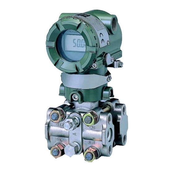
3. COMPONENT NAMES COMPONENT NAMES Vertical impulse piping type Process connection Pressure-detector section (Note 1) Process connector Horizontal impulse piping type Cover External indicator External indicator flange (Note 1) conduit connection (Note 1) conduit connection Terminal box cover Conduit connection CPU assembly Integral (Note 1) -
Page 21: Installation
4. INSTALLATION INSTALLATION 4.1 Precautions Vertical pipe mounting Before installing the transmitter, read the cautionary notes in Section 2.4, “Selecting the Installation Location.” For additional information on the ambient Transmitter conditions allowed at the installation location, refer to mounting bolt Section 10.1 “Standard Specifications.”... -
Page 22: Changing The Process Connection
4. INSTALLATION Vertical pipe mounting 4.3 Changing the Process Con- (Process connector upside) nection The transmitter is shipped with the process connection specified at the time of ordering. To make a change such as modifying the drain (vent) plug(s) attached to U-bolt nut Mounting bracket the upside of the cover flange on shipment to be... -
Page 23: Rotating Transmitter Section
4. INSTALLATION 4.4 Rotating Transmitter Section 4.5 Changing the Direction of Integral Indicator The DPharp transmitter section can be rotated in 90° segments. 1) Remove the two Allen screws that fasten the IMPORTANT transmitter section and capsule assembly, using the Allen wrench. -
Page 24: Installing Impulse Piping
5. INSTALLING IMPULSE PIPING INSTALLING IMPULSE PIPING 5.1 Impulse Piping Installation 5.1.2 Routing the Impulse Piping Precautions (1) Process Pressure Tap Angles The impulse piping that connects the process outputs to If condensate, gas, sediment or other extraneous the transmitter must convey the process pressure material in the process piping gets into the impulse accurately. -
Page 25: Impulse Piping Connection Examples
5. INSTALLING IMPULSE PIPING (3) Impulse Piping Slope 5.2 Impulse Piping Connection The impulse piping must be routed with only an Examples upward or downward slope. Even for horizontal Figure 5.2 shows examples of typical impulse piping routing, the impulse piping should have a slope of at connections. -
Page 26: Wiring
6. WIRING WIRING 6.1 Wiring Precautions 6.3 Connections of External Wiring to Terminal Box 6.3.1 Power Supply Wiring Connection IMPORTANT Connect the power supply wiring to the SUPPLY + • Lay wiring as far as possible from electrical and – terminals. noise sources such as large capacity transform- ers, motors, and power supplies. -
Page 27: Check Meter Connection
6. WIRING (2) Intrinsically Safe Type 6.3.4 Check Meter Connection For intrinsically safe type, a safety barrier must be Connect the check meter to the CHECK + and – included in the loop. terminals (use hooks). • A 4 to 20 mA DC output signal from the CHECK + Hazardous Location Nonhazardous Location and –... -
Page 28: Flameproof Type
6. WIRING 6.5 Grounding (2) Flameproof Type Wire cables through a flameproof packing adapter, or Grounding is always required for the proper operation using a flameproof metal conduit. of transmitters. Follow the domestic electrical require- Wiring cable through flameproof packing adapter. ments as regulated in each country. -
Page 29: Operation
7. OPERATION OPERATION 7.1 Preparation for Starting Operation The Model EJA310A, EJA430A and EJA440A Vent plug (Fill plug) pressure transmitter measures the pressure of liquids, gases, and steam. This section describes the operation Tap valve procedure for the EJA430A as shown in Figure 7.1 (vertical impulse piping type, high-pressure connection: right side) when measuring a pressure. -
Page 30: Zero Point Adjustment
7. OPERATION Using the integral indicator 7.2 Zero Point Adjustment • If the wiring system is faulty, the display stays blank. Adjust the zero point after operating preparation is • If the transmitter is faulty, an error code will appear completed. -
Page 31: When You Can Obtain Low Range Value From Actual Measured Value Of 0% (0 Kpa, Atmospheric Pressure)
7. OPERATION 7.2.1 When you can obtain Low Range 7.2.2 When you cannot obtain Low Range Value from actual measured value Value from actual measured value of 0% (0 kPa, atmospheric pres- of 0%; sure); Convert the actual measured value obtained by a digital For pressure measurement using gauge pressure manometer or a glass gauge into %. -
Page 32: Starting Operation
7. OPERATION 7.3 Starting Operation 7.5 Venting or Draining Transmit- ter Pressure-detector Section After completing the zero point adjustment, follow the procedure below to start operation. Since this transmitter is designed to be self-draining and self-venting with vertical impulse piping connec- 1) Confirm the operating status. -
Page 33: Venting Gas
7. OPERATION 7.5.2 Venting Gas 6) Press the range-setting push-button. The integral indicator then displays “HSET.” 1) Gradually open the vent screw to vent gas from the (Note 1) 7) Apply a pressure of 3 MPa to the transmitter. transmitter pressur-detector section. (See Figure 8) Turn the external zero-adjustment screw in the 7.5.2.) desired direction. -
Page 34: Brain Terminal Bt200 Operation
8. BRAIN TERMINAL BT200 OPERATION BRAIN TERMINAL BT200 OPERATION The DPharp is equipped with BRAIN communica- 8.2 BT200 Operating Procedures tions capabilities, so that range changes, Tag No. setup, monitoring of self-diagnostic results, and zero 8.2.1 Key Layout and Screen Display point adjustment can be handled by remote control Figure 8.2.1a shows the arrangement of the operating via BT200 BRAIN TERMINAL or CENTUM CS... -
Page 35: Operating Key Functions
8. BRAIN TERMINAL BT200 OPERATION 8.2.2 Operating Key Functions Use the function key [F1] to enter symbols. CODE The following symbols will appear in sequence, one (1) Alphanumeric Keys and Shift Keys at a time, at the cursor each time you press [F1] You can use the alphanumeric keys in conjunction CODE: with the shift keys to enter symbols, as well as... -
Page 36: Calling Up Menu Addresses Using The Operating Keys
FEED 4. LCD contrast setting 5. Adjusting printout tone (UTIL) (BT200-P00 only) PARAM 01:MODEL EJA430A-DA INITIAL 02:TAG NO. FUNC DATA YOKOGAWA 1.MENU (ESC) SCREEN 03:SELF CHECK 2.UPLOAD TO BT200 GOOD 3.DOWNLOAD TO INST 4.PRINT ALL DATA HOME (SET) (ADJ) (HOME MENU SCREEN) -
Page 37: Setting Parameters Using The Bt200
8. BRAIN TERMINAL BT200 OPERATION 8.3 Setting Parameters Using the BT200 8.3.1 Parameter Summary Instruments to which applicable: F: Differential pressure transmitters EJA110A, EJA120A, and EJA130A P: Pressure transmitters EJA310A, EJA430A, EJA440A, EJA510A, and EJA530A L: Liquid level transmitters EJA210A and EJA220A Applica- Rewrita- bility... - Page 38 8. BRAIN TERMINAL BT200 OPERATION Applica- Rewrita- bility Item Description Remarks Default Value bility AUX SET 1 Auxiliary setting data 1 Menu name — D30 TEMP UNIT Temperature setting deg C/deg F deg C units D31 STAT. P. UNIT Static pressure setting Selected from mmH O, mmAq, As specified when ordered.
-
Page 39: Parameter Usage And Selection
8. BRAIN TERMINAL BT200 OPERATION 8.3.2 Parameter Usage and Selection IMPORTANT Before describing the procedure for setting param- If the transmitter is turned off within 30 seconds eters, we present the following table showing how after parameters have been set, the set data the parameters are used and in what case. -
Page 40: Setting Parameters
8.3.3 Setting Parameters This is the panel for confirming C10:TAG NO. Set or change the parameters as necessary. After YOKOGAWA set data. The set data items flash. FIC-1a completing these, do not fail to use the “DIAG” key When all items have been confir-... -
Page 41: Damping Time Constant Setup
8. BRAIN TERMINAL BT200 OPERATION b. Setting Calibration Range Lower • Example 2: With present settings of 0 to 30 kPa, Range Value and Higher Range Value set the Higher range value to10 kPa. (C21: LOW RANGE, C22: HIGH RANGE) Set 10. -
Page 42: Output Signal Low Cut Mode Setup
8. BRAIN TERMINAL BT200 OPERATION (4) Output Signal Low Cut Mode Setup (5) Integral Indicator Scale Setup (D10: LOW CUT, D11: LOW CUT MODE) The following 5 displays are available for integral Low cut mode can be used to stabilize the output indicators. - Page 43 8. BRAIN TERMINAL BT200 OPERATION b. Setting User-set Engineering Unit % indication and User-set engineering (D21: DISP UNIT) input pressure unit display This parameter allows entry of the engineering units indication to be displayed on the BT200. When the instrument is shipped, this is set as specified in the order.
-
Page 44: Unit Setup For Displayed Temperature
8. BRAIN TERMINAL BT200 OPERATION (6) Unit Setup for Displayed Temperature (8) Output Status Display/Setup when a CPU (D30: TEMP UNIT) Failure (D52: BURN OUT) When the instrument is shipped, the temperature units This parameter displays the status of 4 to 20 mA DC are set to degC. -
Page 45: Range Change While Applying Actual Inputs
8. BRAIN TERMINAL BT200 OPERATION (10) Range Change while Applying Actual Note that changing the higher range value does not Inputs (H10: AUTO LRV, H11: AUTO cause the lower range value to change but does HRV) change the span. This feature allows the lower and higher range values to be set up automatically with the actual input •... - Page 46 8. BRAIN TERMINAL BT200 OPERATION (a) Follow the procedure below when setting the (b)-2 Follow the procedure below to use J11: ZERO present output to 0% (4 mA). DEV. Present output is 41.0%. Output is 0.5%. A10:OUTPUT (%) A10:OUTPUT (%) 41.0 % 0.5 % Output error = 40.0 –...
-
Page 47: Test Output Setup
8. BRAIN TERMINAL BT200 OPERATION (12) Test Output Setup (K10: OUTPUT X%) (c) Zero Point Adjustment Using the External Zero Adjustment Screw This feature can be used to output a fixed current from 3.2 mA (–5%) to 21.6 mA (110%) for loop •... -
Page 48: Displaying Data Using The Bt200
• Example 2: Setting entry errors A20:AMP TEMP The initial data panel shows the PARAM 01:MODEL EJA510A-DC result of current transmitter F0834.EPS 02:TAG NO. YOKOGAWA diagnostics. 03:SELF CHECK 8.4.2 Display Transmitter Model and ERROR Specifications PARAM Press the (DIAG) key in the... -
Page 49: Checking With Integral Indicator
8. BRAIN TERMINAL BT200 OPERATION (2) Checking with Integral Indicator • Example 3: Checking the history of the errors Connect the BT200 to the MENU NOTE J:ADJUST transmitter, and call item “P.” K:TEST M:MEMO P:RECORD If an error is detected in the self-diagnostic, an error number is displayed on the integral HOME indicator. -
Page 50: Errors And Countermeasures
8. BRAIN TERMINAL BT200 OPERATION 8.5.2 Errors and Countermeasures The table below shows a summary of error messages. Table 8.5.1 Error Message Summary Integral Output Operation Indicator BT200 Display Cause Countermeasure during Error Display None GOOD ---- ERROR Capsule problem. Outputs the signal Replace capsule. -
Page 51: Maintenance
9. MAINTENANCE MAINTENANCE 9.1 Overview 9.2 Calibration Instruments Se- lection WARNING Table 9.2.1 shows the instruments required for calibra- tion. Select instruments that will enable the transmitter Since the accumulated process fluid may be to be calibrated or adjusted to the required accuracy. toxic or otherwise harmful, take appropriate care The calibration instruments should be handled carefully to avoid contact with the body, or inhalation of... - Page 52 0.1% level, there are difficulties in calibration to this level in the field. For calibration to the 0.1% level, contact Yokogawa representatives from which the instrument was purchased or the nearest Yokogawa office.
-
Page 53: Disassembly And Reassembly
Phillips screwdriver JIS B4633, No. 2 a transmitter. If such modification is absolutely Slotted screwdriver required, contact Yokogawa. Allen wrenches JIS B4648 One each, nominal 3 and 5 mm Allen wrenches This subsection describes the procedure for replacing... -
Page 54: Replacing The Cpu Board Assembly
9. MAINTENANCE Attaching the Integral Indicator 9.4.2 Replacing the CPU Board Assembly Integral indicator can be installed in the following three This subsection describes the procedure for replacing directions. the CPU assembly. (See Figure 9.4.2) Removing the CPU Assembly 1) Remove the cover. If an integral indicator is mounted, refer to Subsection 9.4.1 and remove the indicator. -
Page 55: Cleaning And Replacing The Capsule Assembly
6) Remove the capsule assembly. Yokogawa. 7) Clean the capsule assembly or replace with a new The user is permitted, however, to replace a one. -
Page 56: Replacing The Process Connector Gaskets
Since some problems have Allen screw complex causes, these flow charts may not identify all. If you have difficulty isolating or correcting a problem, contact Yokogawa service personnel. 9.5.1 Basic Troubleshooting Capsule gasket First determine whether the process variable is actually... -
Page 57: Troubleshooting Flow Charts
Fully open tap and stop valves, and Adjust the zero point. fully close drain valve. Contact Yokogawa service personnel. F0908.EPS Is there any pressure leak? Fix pressure leaks, paying particular attention to connections for impulse piping,pressure-detector section, etc. - Page 58 Provide lagging and/or cooling, or allow adequate ventilation. Were appropriate instruments used for calibration? Refer to Section 9.2 when selecting instruments for calibration. Is output adjusted correctly? Adjust the output. Contact Yokogawa service personnel. F0909.EPS IM 01C21D01-01E...
-
Page 59: General Specifications
10. GENERAL SPECIFICATIONS 10. GENERAL SPECIFICATIONS 10.1 Standard Specifications External Zero Adjustment “ ”: Refer to IM 01C22T02-01E for F OUNDATION External zero is continuously adjustable with Fieldbus communication type and IM 01C22T03- 0.01% incremental resolution of span. Span may 00E for PROFIBUS PA communication type be adjusted locally using the digital indicator with marked with “... - Page 60 10. GENERAL SPECIFICATIONS Where: Supply Voltage “ ”: L = length in meters or feet 10.5 to 42 V DC for general use and flameproof type R = resistance in (including barrier resistance) 10.5 to 32 V DC for lightning protector (Optional code /A) C = cable capacitance in pF/m or pF/ft 10.5 to 30 V DC for intrinsically safe, Type n, = maximum shunt capacitance of receiving...
-
Page 61: Model And Suffix Codes
10. GENERAL SPECIFICATIONS 10.2 Model and Suffix Codes Model EJA310A Description Model Suffix Codes ..... Absolute pressure transmitter EJA310A -D ....Output Signal 4 to 20 mA DC with digital communication (BRAIN protocol) (Note 1) - Page 62 10. GENERAL SPECIFICATIONS Model EJA430A Suffix Codes Model Description ......Gauge pressure transmitter EJA430A -D ..... . 4 to 20 mA DC with digital communication (BRAIN protocol) Output Signal (Note 1)
- Page 63 10. GENERAL SPECIFICATIONS Model EJA440A Model Suffix Codes Description ..... . . Gauge pressure transmitter EJA440A -D ..... 4 to 20 mA DC with digital communication (BRAIN protocol) Output Signal (Note 1)
-
Page 64: Optional Specifications
10. GENERAL SPECIFICATIONS 10.3 Optional Specifications For F Fieldbus explosion protected type, see IM 01C22T02-01E. OUNDATION For PROFIBUS PA explosion protected type, see IM 01C22T03-00E. Item Description Code FM Explosionproof Approval Explosionproof for Class I, Division 1, Groups B, C and D Dust-ignitionproof for Class II/III, Division 1, Groups E, F and G Hazardous (classified) locations, indoors and outdoors (NEMA 4X) Temperature class: T6... - Page 65 10. GENERAL SPECIFICATIONS Item Description Code CSA Explosionproof Approval Certificate: 1089598 Explosionproof for Class I, Division 1, Groups B, C and D Dustignitionproof for Class II/III, Division 1, Groups E, F and G Division2 ‘SEALS NOT REQUIRED’ , Temp. Class: T4, T5, T6 Encl Type 4x Max.
- Page 66 10. GENERAL SPECIFICATIONS Item Description Code Amplifier cover only Color change Painting Amplifier cover and terminal cover, Munsell 7.5 R4/14 Coating change Epoxy resin-baked coating Transmitter power supply voltage: 10.5 to 32 V DC (10.5 to 30 V DC for intrinsically safe type, 9 to 32 V DC for F Fieldbus and PROFIBUS PA communication type.) Lightning protector...
-
Page 67: Dimensions
10. GENERAL SPECIFICATIONS 10.4 Dimensions Model EJA310A and EJA430A Vertical Impulse Piping Type Process connector upside (INSTALLATION CODE ‘6’) (For CODE ‘2’, ‘3’ or ‘7’, refer to the notes below.) Process connector External indicator (Optional) conduit connection 259(10.20) Blind plug (Optional) 197 (7.76) 110 (4.33) - Page 68 10. GENERAL SPECIFICATIONS Model EJA440A The data in the drawing is basically common to C capsule and D capsule, except where the difference is noted. Vertical Impulse Piping Type Process connector upside (INSTALLATION CODE ‘6’) (For CODE ‘2’, ‘3’ or ‘7’, refer to the notes below.) Unit: mm (approx.
-
Page 69: Parts List
(Note 1) Applicable for BRAIN and HART protocol versions (Output signal code D and E). For F Fieldbus protocol OUNDATION version (Output signal code F), consult Yokogawa local office. CMPL 01C21A01-02E All Rights Reserved, Copyright © 1997, Yokogawa Electric Corporation. - Page 70 4–1 10–1 12–1 12–2 13–1 For EJA440A 11–2 For EJA310A low pressure side cover flange 10–2 21–3 13–3 21–2 4–2 13–2 12–3 CMPL 01C21D00-01E All Rights Reserved, Copyright © 1999, Yokogawa Electric Corporation. 5th Edition: July 2001(YK) Yokogawa Electric Corporation...
- Page 71 Vertical Impulse Piping Type Low pressure side 21–1 13–1 11–1 12–1 4–1 10–1 For EJA440A For EJA310A low pressure side 13–3 cover flange 13–2 11–2 12–3 21–3 4–2 21–2 10–2 CMPL 01C21D00-01E July 2001 Subject to change without notice. Printed in Japan.
- Page 72 Item Part No. Description — Capsule Assembly (see Table 1, Table 2 and Table 3 on page 5) (Note 1) F9300AJ O-Ring Below Gasket (for EJA310A and EJA430A with F9340GA Teflon-coated SUS316L Stainless Steel Wetted Parts Material code S) F9340GC Teflon-coated SUS316L Stainless Steel (degreased) F9340GE PTFE Teflon...
- Page 73 (However, see Table 1, Table 2 and Table 3 in case of Optional code/K2 or K6) (Note 2) In case of degrease cleansing treatment (Optional code/K1, K2, K5 or K6), consult YOKOGAWA local office. (Note 3) The Plug Qty is 1 for Vertical Impulse Piping Type.
- Page 74 Capsule Assembly Part Number EJA310A Table 1. EJA310A Capsule Assembly Part Number (Item 1) For General-use type, Flameproof type and Intrinsically safe type Installation of High Pressure Capsule Part No. Part No. (*1) (*2) Transmitter Side Code F9349HA F9352HA Right F9349JA F9352JA Horizontal Impulse...
- Page 75 REVISION RECORD Title: Model EJA310A, EJA430A and EJA440A Absolute Pressure and Gauge Pressure Transmitter Manual No.: IM 01C21D01-01E Edition Date Page Revised Item June 1997 – New publication Mar. 1998 CONTENTS Page 3 • Add REVISION RECORD. • Add ‘NOTE’ notice for F Fieldbus and HART protcol OUNDATION versions.
- Page 76 Edition Date Page Revised Item • Add Optional code /F1, /N1, /N2, /N3, /N4, and /R1. Sep. 2000 10-7 (Continued) CMPL CMPL 1C21A1-02E 4th 5th(Manual Change) • Add part numbers to 7-1 CPU Assembly. F9342AF and F9342AM CMPL 1C21A1-02E 5th •...
Need help?
Do you have a question about the Dpharp vigilantplant EJA310A and is the answer not in the manual?
Questions and answers