Sign In
Upload
Manuals
Brands
YOKOGAWA Manuals
Transmitter
Dpharp EJA118Y
User Manuals: YOKOGAWA Dpharp EJA118Y DP Transmitter
Manuals and User Guides for YOKOGAWA Dpharp EJA118Y DP Transmitter. We have
5
YOKOGAWA Dpharp EJA118Y DP Transmitter manuals available for free PDF download: User Manual, Manual
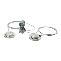
YOKOGAWA Dpharp EJA118Y User Manual (76 pages)
Diaphragm Sealed Differential Pressure Transmitters (Style: S2)
Brand:
YOKOGAWA
| Category:
Transmitter
| Size: 1 MB
Table of Contents
Table of Contents
3
1 Introduction
7
Warranty
8
2 Handling Cautions
9
Model and Specifications Check
9
Unpacking
9
Storage
9
Selecting the Installation Location
10
Pressure Connection
10
Waterproofing of Cable Conduit Connections
10
Restrictions on Use of Radio Transceiver
10
Insulation Resistance and Dielectric Strength Test
11
Installation of Explosion Protected Type
11
FM Approval
11
CSA Certification
13
SAA Certification
14
CENELEC (KEMA)/IEC (KEMA) Certification
15
JIS Certification
17
EMC Conformity Standards
17
3 Component Names
18
4 Installation
19
Precautions
19
Mounting the Diaphragm Seals
19
Transmitter Mounting
20
Affixing the Teflon Film
21
Rotating Transmitter Section
21
5 Wiring
22
Wiring Precautions
22
Selecting the Wiring Materials
22
Connections of External Wiring to Terminal Box
22
Power Supply Wiring Connection
22
External Indicator Connection
22
BRAIN TERMINAL BT200 Connection
23
Check Meter Connection
23
Wiring
23
Loop Configuration
23
General-Use Type and Flameproof Type
23
Intrinsically Safe Type
23
Wiring Installation
24
General-Use Type and Intrinsically Safe Type
24
Flameproof Type (JIS)
24
Grounding
25
Power Supply Voltage and Load Resistance
25
6 Operation
26
Preparation for Starting Operation
26
Zero Point Adjustment
27
When You Can Obtain Low Range Value from Actual Measured Value of 0% (0 Kpa, Atmospheric Pressure)
27
When You Cannot Obtain Low Range Value from Actual Measured Value of 0
27
Starting Operation
28
Shutting down Operation
28
Setting the Range Using the Range-Setting Switch
29
7 Brain Terminal Bt200 Operation
30
BT200 Operation Precautions
30
Connecting the BT200
30
Conditions of Communication Line
30
BT200 Operating Procedures
30
Key Layout and Screen Display
30
Operating Key Functions
31
Alphanumeric Keys and Shift Keys
31
Function Keys
31
Calling up Menu Addresses Using the Operating Keys
32
Setting Parameters Using the BT200
33
Parameter Summary
33
Parameter Usage and Selection
35
Setting Parameters
36
Tag No. Setup
36
Calibration Range Setup
36
Damping Time Constant Setup
37
Output Mode and Integral Indicator Display Mode Setup
38
Output Signal Low Cut Mode Setup
38
Integral Indicator Scale Setup
39
Unit Setup for Displayed Temperature
40
Unit Setup for Displayed Static Pressure
41
Operation Mode Setup
41
Impulse Line Connection Orientation Setup
41
Output Status Display/Setup When a CPU Failure
41
Output Status Setup When a Hardware Error Occurs
41
Bi-Directional Flow Measurement Setup
42
Range Change While Applying Actual Inputs
42
Zero Point Adjustment
43
Test Output Setup
44
User Memo Fields
44
Displaying Data Using the BT200
45
Displaying Measured Data
45
Display Transmitter Model and Specifications
45
Self-Diagnostics
45
Checking for Problems
45
Identifying Problems with BT200
45
Checking with Integral Indicator
46
Errors and Countermeasures
47
8 Maintenance
48
Overview
48
Calibration Instruments Selection
48
Calibration
48
Disassembly and Reassembly
50
Replacing the Integral Indicator
50
Replacing the CPU Assembly
51
Troubleshooting
52
Basic Troubleshooting
52
Troubleshooting Flow Charts
52
9 General Specifications
54
Standard Specifications
54
Model and Suffix Codes
56
Optional Specifications
59
Dimensions
61
Installation and Operating Precautions for Jis Intrinsically Safe Equipment
64
Installation and Operating Precautions for Jis Flameproof Equipment
67
Parts List
71
Customer Maintenance Parts List
73
Advertisement
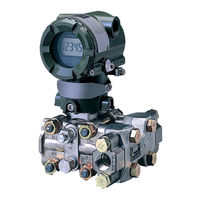
YOKOGAWA Dpharp EJA118Y User Manual (79 pages)
EJA Series Differential Pressure/Pressure Transmitter Fieldbus Communication Type
Brand:
YOKOGAWA
| Category:
Transmitter
| Size: 1 MB
Table of Contents
Table of Contents
2
1 Introduction
5
Regarding this Manual
5
For Safe Use of Product
5
Warranty
6
ATEX Documentation
7
2 Handling Caution
9
Installation of an Explosion-Protected Instrument
9
FM Approval
9
CSA Certification
13
CENELEC ATEX (KEMA) Certification
13
Iecex Certification
17
3 About Fieldbus
18
Outline
18
Internal Structure of EJA
18
System/Network Management VFD
18
Function Block VFD
18
Logical Structure of each Block
18
Wiring System Configuration
18
4 Getting Started
19
Connection of Devices
19
Host Setting
20
Bus Power on
21
Integration of DD
21
Reading the Parameters
21
Continuous Record of Values
22
Generation of Alarm
22
5 Configuration
23
Network Design
23
Network Definition
23
Definition of Combining Function Blocks
24
Setting of Tags and Addresses
25
Communication Setting
26
VCR Setting
26
Function Block Execution Control
27
Block Setting
27
Link Object
27
Trend Object
28
View Object
28
Function Block Parameters
30
Transducer Block Parameters
31
6 In-Process Operation
32
Mode Transition
32
Generation of Alarm
32
Indication of Alarm
32
Alarms and Events
32
Simulation Function
33
7 Device Status
34
8 General Specifications
36
Standard Specifications
36
Optional Specifications
37
Appendix 1. List of Parameters for each Block of the Eja
39
A1.1 Resource Block
39
A1.2 al Function Block
41
A1.3 Transducer Block
43
Appendix 2. Application, Setting and Change of Basic Parameters
45
A2.1 Applications and Selection of Basic Parameters
45
A2.2 Setting and Change of Basic Parameters
46
A2.3 Setting the AI1 Function Block
46
A2.4 Setting the AI2 Function Block
48
A2.5 Setting the Transducer Block
48
Appendix 3. Operation of each Parameter in Failure Mode
50
Appendix 4. Pid Block
52
A4.1 Function Diagram
52
A4.2 Functions of PID Bock
52
Control Algorithm
52
A4.4.2 PID Control Parameters
52
A4.5 Control Output
52
A4.7 Control Action Bypass
52
A4.8 Feed-Forward
52
A4.10 Bumpless Transfer
52
A4.11 Setpoint Limiters
52
A4.11.2 When PID Block Is in Cas or Rcas Mode
57
A4.17.1 Shed_Opt
59
A4.18 Alarms
59
A4.18.1 Block Alarm (BLOCK_ALM)
59
A4.18.2 Process Alarms
59
A4.19 Example of Block Connections
60
A4.19.1 View Object for PID Function Block
60
Appendix 5. Link Master Functions
62
A5.1 Link Active Scheduler
62
A5.2 Link Master
62
A5.3 Transfer of las
63
A5.4 LM Functions
64
A5.5 LM Parameters
65
A5.5.1 LM Parameter List
65
A5.5.2 Descriptions for LM Parameters
67
A5.6 Faqs
69
Appendix 6. Software Download
70
A6.2 Specifications
70
A6.1 Benefits of Software Download
70
A6.3 Preparations for Software Downloading
70
A6.4 Flow of Software Download
71
A6.5 Download Files
71
A6.6 Steps after Activating a Field Device
72
A6.7 Troubleshooting
73
A6.8 Resource Block's Parameters Relating to Software Download
73
A6.9 View Objects Altered by Software Download
75
A6.10 System/Network Management VFD Parameters Relating to Software Download
76
A6.11 Comments on System/Network Management VFD Parameters Relating to Software Download
77
A6.11 Comments on System/Network Management VFD Parameters
77
Relating to Software Download
77
Revision Record
79
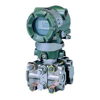
YOKOGAWA Dpharp EJA118Y User Manual (40 pages)
EJA Series Differential Pressure and Pressure Transmitters
Brand:
YOKOGAWA
| Category:
Transmitter
| Size: 3 MB
Table of Contents
Table of Contents
1
Regarding this Manual
3
1 Introduction
4
For Safe Use of Product
4
Warranty
4
ATEX Documentation
6
2 Handling Cautions
7
Model and Specifi Cations Check
7
Selecting the Installation Location
7
Pressure Connection
8
Installation of Explosion Protected Type
8
Wiring
10
EMC Conformity Standards
15
PED (Pressure Equipment Directive)
15
Low Voltage Directive
16
3 Installation
17
Mounting
17
Mounting the Diaphragm Seals
17
Diaphragm Seals Installation Consideration
18
Affi Xing the Tefl on Film
19
Rotating Transmitter Section
20
Changing the Direction of Integral Indicator
20
4 Installing Impulse Piping
21
Connecting Impulse Piping to the Transmitter
21
Impulse Piping Installation Precautions
21
Routing the Impulse Piping
22
Impulse Piping Connection Examples
23
Process Piping Installation Precautions
24
5 Wiring
25
Wiring Precautions
25
Connections of External Wiring to Terminal Box
25
Wiring Installation
26
Grounding
27
Power Supply Voltage and Load Resistance
27
6 Operation
28
Preparation for Starting Operation
28
Zero Point Adjustment
29
7 Errors and Countermeasures
30
8 Parameter Summary
31
Advertisement
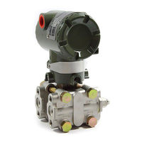
YOKOGAWA Dpharp EJA118Y Manual (40 pages)
EJA Series Differential Pressure and Pressure Transmitters
Brand:
YOKOGAWA
| Category:
Transmitter
| Size: 5 MB
Table of Contents
Table of Contents
1
Regarding this Manual
3
1 Introduction
4
For Safe Use of Product
4
Warranty
4
ATEX Documentation
6
2 Handling Cautions
7
Model and Specifications Check
7
Selecting the Installation Location
7
Pressure Connection
8
Installation of Explosion Protected Type
8
Wiring
10
EMC Conformity Standards
15
PED (Pressure Equipment Directive)
15
Low Voltage Directive
16
3 Installation
17
Mounting
17
Mounting The Diaphragm Seals
17
Diaphragm Seals Installation Consideration
18
3.4 Affixing The Teflon Film
19
Rotating Transmitter Section
20
Changing the Direction of Integral Indicator
20
4 Installing Impulse Piping
21
Impulse Piping Installation Precautions
21
Routing the Impulse Piping
22
Impulse Piping Connection Examples
23
Process Piping Installation Precautions
24
5 Wiring
25
Wiring Precautions
25
Connections of External Wiring to Terminal Box
25
Wiring Installation
26
Grounding
27
Power Supply Voltage and Load Resistance
27
6 Operation
28
Preparation for Starting Operation
28
Zero Point Adjustment
29
7 Errors and Countermeasures
30
8 Parameter Summary
31
YOKOGAWA Dpharp EJA118Y User Manual (31 pages)
EJA Series, HART Protocol
Brand:
YOKOGAWA
| Category:
Transmitter
| Size: 0 MB
Table of Contents
Table of Contents
2
Preliminary
3
1 Zero Point Adjustment
4
Using the HART Communicator
5
Using the Transmitter Zero-Adjustment Screw
5
Auto LRV (Change Low Range Value)
6
Using Model 275 - Apply Values
6
Setting the Range Using the Range-Setting Switch
6
2 Hart Communicator Operation
8
Conditions of Communication Line
8
Interconnection between Dpharp and HART Communicator
8
Communication Line Requirements
8
Basic Operation of the HART Communicator (Model 275)
9
Keys and Functions
9
Display
10
Calling up Menu Addresses
10
Entering, Setting, and Sending Data
11
Parameters
12
Parameter Usage and Selection
12
Menu Tree
13
Setting Parameters
14
Tag no
14
Unit
14
Range Change
14
Output Mode (Linear/Sq Root)
15
Damping Time Constants
16
Output Signal Low Cut Mode Setup
16
Bi-Directional Flow Measurement
17
Integral Indicator Display Mode
17
Integral Indicator Scale
17
Unit for Displayed Temperature
19
Unit for Displayed Static Pressure
19
Test Output
19
Sensor Trim
20
Trim Analog Output
21
Burst Mode
23
Multidrop Mode
23
External Switch Mode
24
Software Write Protect
24
Hardware Write Protect and Burnout Direction(with Optional Code /F1)
26
H2O Unit Select
26
Self-Diagnostics
26
Checking for Problems
26
Identify Problems with HART Communicator
26
Checking with Integral Indicator
27
3 Parameter Lists
29
Revision Record
31
Advertisement
Related Products
YOKOGAWA Dpharp EJA118N
YOKOGAWA Dpharp vigilantplant EJA110A
YOKOGAWA EJA118
YOKOGAWA Dpharp vigilantplant EJA115
YOKOGAWA Dpharp EJA118W
YOKOGAWA DPharp EJA110E
YOKOGAWA DPharp EJA118E
YOKOGAWA DPharp EJA115E
YOKOGAWA DPharp EJA110
YOKOGAWA DPharp EJA120
YOKOGAWA Categories
Measuring Instruments
Test Equipment
Transmitter
Controller
Media Converter
More YOKOGAWA Manuals
Login
Sign In
OR
Sign in with Facebook
Sign in with Google
Upload manual
Upload from disk
Upload from URL