Table of Contents
Advertisement
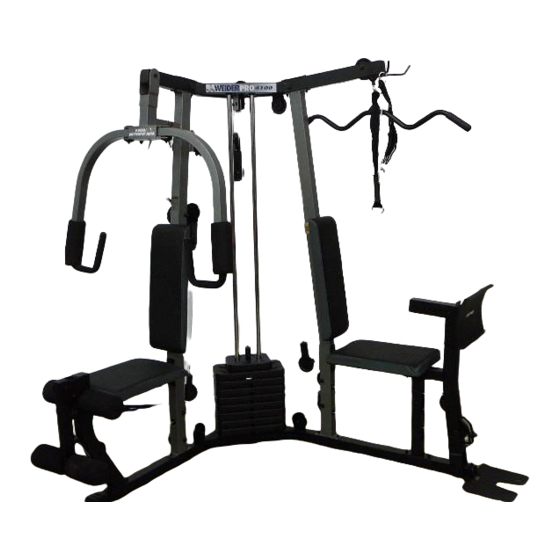
WELDER PR@4
Model No. 831.159820
Serial No.
Write the serial number in the
space above for reference.
r
Sedal Number Decal (under seat)
E_<IE_
R_
I S _
EQUIPMENT
[Olll
Ill
ROB
_ I
H
I_LPLI
N
E
!
1-800-736-6879
USER'S MANUAL
SEARS, ROEBUCK AND CO.
HOFFMAN ESTATES, IL 60179
www.weiderfitness.com
new products,
prizes,
fitness tips, and much morel
Advertisement
Table of Contents

Related Manuals for Weider Pro 4100


Summary of Contents for Weider Pro 4100
- Page 1 WELDER PR@4 Model No. 831.159820 Serial No. USER'S MANUAL Write the serial number in the space above for reference. Sedal Number Decal (under seat) E_<IE_ I S _ EQUIPMENT [Olll I_LPLI 1-800-736-6879 SEARS, ROEBUCK AND CO. HOFFMAN ESTATES, IL 60179 www.weiderfitness.com new products, prizes,...
-
Page 2: Table Of Contents
TABLE OF CONTENTS IMPORTANT PRECAUTIONS ............. BEFORE YOU BEGIN ..............ASSEMBLY ................ADJUSTMENTS ..............WEIGHT RESISTANCE CHART ............CABLE DIAGRAM ..............EXERCISE GUIDELINES ..............ORDERING REPLACEMENT PARTS ..........Back Cover FULL 90 DAY WARRANTY ............Back Cover Note: A PART IDENTIFICATION CHART and a PART LIST/EXPLODED DRAWING are attached in the center of this manual. -
Page 3: Important Precautions
IMPORTANT PRECAUTIONS... -
Page 4: Overview
Thank you for selecting the versatile WELDER• PRO 1-800-736-6879, Monday through Saturday, 7 a.m. 4100 weight system. The PRO 4100 weight system until 7 p.m. Central lime (excluding holidays). To help offers a selection of weight stations designed to devel- us assist you, please note the product model number op every major muscle group of the body. -
Page 5: Assembly
ASSEMBLY • As you assemble the weight system, make sure all parts are odented as shown in the drawings. • For help identifying small pads, use the PART ON C An Allen wrench and the following tools (not included) are required for assembly: •... - Page 6 Attach the Base Plate (37) to the Left Base (2) with a 3/8" x 5 1/2" Bolt (58) and a 3/8" Nylon Locknut (70). Attach the Left Upright (7) to the Left Base (2) with the two indicated 5/16" x 2 1/2" Carriage Bolts (57) and two 5/16"...
- Page 7 Attach the Right Seat Frame (5) to the Right Leg (73) with two 5/16" x 3 1/4" Bolts (59), two 5/16" Washers (26), and two 5/16" Nylon Locknuts (71). Attach the Right Seat Frame (5) to the Right Upright (6) with two 5/16" x 3 1/4" Bolts (59), two 5/16"...
- Page 8 Slide the eight Weights (72) onto the Weight Lubricate Guides (20) with the pin grooves on the side shown. Press the Weight Tube Bumper (32) into the bot- tom of the Weight Tube (82). Insert the Weight Tube into the center hole in the stack of Weights (72).
- Page 9 11. Press the two Weight Guide Bushings (44) into the Center Top Frame (14), Slide the Center Top Frame onto the Weight Guides (20). Attach the Center Top Frame (14) to the Right Top Frame (8) with two 5116"x 2 3/4" Bolts (60), two 5/16"...
- Page 10 14. Lubricate a 3/8"x 3" Button Head Bolt (97) and Lubricate both sides of two Plastic Washers (55) with Welded grease. Attach the Right Butterfly Arm (11) to the Butterfly Frame (9) with the Bolt, the two Plastic Washers, two Butterfly Caps (54), two 3/8" wash- ers (75), and a 3/8"...
-
Page 11: Cable Assembly
Locate the High Cable (45). Route the Cable up through the Left Top Frame (3) and around a 3 1/2" Pulley (38), Attach the Pulley inside the Top Frame with a 3/8" x 2 3/4" Bolt (81), two 3/6" Washers (75), two 1/2" Spacers (34), and a 3/8" Nylon Locknut (70). - Page 12 21. Wrap the High Cable (45) around a 3 1/2" Pulley (38). Attach the Pulley at the forward hole, inside of the bracket on the Center Top Frame (14) with a 3/8" x 1 3/4" Bolt (66) and a 3/8" Nylon Locknut (70).
- Page 13 25. Route the Leg Press Cable (95) through the Left Leg (36) and the Left Upright (7) as shown. Wrap the Cable around a 3 1/2" Pulley (38). Attach the Pulley inside the Upright with a 318"x 2 3/4" Bolt (81), two 3/8"...
- Page 14 29. Wrap the Butterfly Cable (46) around a =V"-Pulley (39). Attach the Pulley and a Long Cable Trap (40) to the bracket on the Right Upright (6) with a 318" x 2 1/2" Bolt (63) and a 3/8" Nylon Locknut (70).
- Page 15 33. Locate the Leg Lever Cable (96). Route the eyelet end of the Cable through the Right Leg (73) and attach it to the Leg Lever (4) with a 5/16" x 1" Shoulder Bolt (78) and a 5116" Nylon Locknut (71).
- Page 16 37. Remove the preettached 3 112" Pulley (not shown) from the "U"-Bracket (85). Attach the end of the Leg Lever Cable (96) to the other =U"-Bracket (85) with a 1/4" Washer (35) and a 1/4" Nylon Locknut (65). Note: Do not completely tighten the Nylon Locknut;...
- Page 17 41. Wrap the Low Cable (47) around a 3 1/2" Pulley (38). Attach the Pulley to the indicated bracket on the Left Base (2) with a 3/8" x 2" Bolt (62) and a 3/8" Nylon Locknut (70). 42. Wrap the Low Cable (47) around a 3 1/2" Pulley (38).
- Page 18 45. Wrap the Low Cable (47) around a 3 1/2" Pulley (38). Attach the Pulley to the indicated bracket on the Right Base (1) with a 3/8" x 2" Bolt (62) and a 3/8" Nylon Locknut (70). l i u 46.
- Page 19 ::_ ::_:_s _ .'_" "_" ""_ "' " "" " _ -•_ _'""_- ""_• _ _- • "_'1 ¸ "_@ 49. Attach a Seat (16) to the Right Seat Frame (5) with a 1/4" x 2 1/2" Bolt (90), a 1/4" Washer (35), and two 1/4"...
- Page 20 53. Insert the two Locking Pins (53) into the Butterfly Frame (9). Attach the tether on the Pins to the Butterfly Frame with a #8 x 3/4" Screw (68). Do not fully tighten the Screw. 54. Make sure that all parts have been properly tightened. The use of all remaining parts will be explained in ADJUSTMENTS, starting on the following page.
-
Page 21: Adjustments
ADJUSTMENTS This section explains how to adjust the weight system. See the EXERCISE GUIDELINES on page 26 for impor- tant information about how to get the most benefit from your exercise program. Also, refer to the accompanying exercise guide to see the correct form for each exemise. Make sure all parts are properly tightened each time the weight system is used. - Page 22 TIGHTENING THE CABLES Woven cable, the type of cable used on the weight system, can stretch slightlywhen it is first used. If there is slack in the cables before resistance is felt, the cables should be tightened. See drawing A. Slack can be removed by moving the 3 1/2"...
-
Page 23: Weight Resistance Chart
WEIGHT RESISTANCE CHART The chart below shows the approximate weight resistance at each exercise station. "Top"refers to the 6 Ib, top weight. The other numbers refer to the 12.5 lb. weight plates. Weight resistance shown for the butterfly arm sta- tion is for each butterfly arm. -
Page 24: Cable Diagram
CABLE DIAGRAMS The cable diagrams below show the proper muting of the High Cable (45), the Butterfly Cable (46), the Low Cable (47), the Leg Press Cable (95), and the Leg Lever Cable (96). Use the diagrams to make sure that the cables and the cable traps have been assembled correctly. - Page 25 Leg Press Cable (95) Leg Lever Cable (96) CABLE ID CHART -- (46) 47 3/7" -- (96) 95 112" -- (95) 148 1/4" -_ _ -- (47) 276 3/4" _" _ -- (45) 116 3/4"...
-
Page 26: Exercise Guidelines
EXERCISE GUIDELINES THE FOUR BASIC TYPES OF WORKOUTS PERSONALIZING YOUR EXERCISE PROGRAM Muscle Building Determining the exact length of time for each workout, To increase the size and strength of your muscles, as well as the number of repetitions or sets completed, push them close to their maximum capacity. - Page 27 Rest for a short period of time after each set. The slowly as you stretch and do not bounce. Ease into ideal resting periods are: each stretch gradually and go only as far as you can • Rest for three minutes after each set for a muscle without strain.
- Page 28 This chart is provided to help you identify the small parts used in assembly. The number in parenthesis below each part refers to the key number of the part from the PART LIST in the center of this manual. Important: Some parts may have been pre-assembled for shipping, If you cannot find a part In the parts bags, check to see if It has been pre-aseembled.
- Page 29 PART IDENTIFICATION CHART--Model No. 831.159820 R0802C 1/4" x 2 1/2" Bolt (90) 3/8" x 2" Bolt (62) 5/16"x 2 1/2" Bolt (89) 1/4" Nylon Locknut (65) 3/8" Nylon Jamnut (50) 5/16" x 1 3/4" Bolt (69) 3/8" Washer (75) 3/8" x 2 1/2" Bolt (63) 3/8"...
- Page 30 EXPLODED DRAWING--Model No. 831.159820 R08020 ' 39 '": fTJ.--S68 , :-" .--- _..54 50"J_ 5(T,e : 75 .-""...
- Page 31 PART LIST--Model No. 831.159820 R08O2C Key No. Qty. Description Key No. Qty. Description Right Base Cable Clip Left Base Locking Pin Left Top Frame Butterfly Cap Leg Lever Plastic Washer Right Seat Frame Double "U"-Bracket Right Updght 5/16" x 2 1/2" Carriage Bolt Left Upright 3/8"...
- Page 32 • or you need to schedule repair • The MODEL NUMBER of the product (831.159820) service • The NAME of the product (WEIDEFP PRO 4100 weight system) call our toll-free HELPLINE 1-800-736-6879 • The KEY NUMBER and DESCRIPTION of the PART (see the...