Heatilator EC36 Installation & Operating Instructions Manual
Woodburning fireplace
Hide thumbs
Also See for EC36:
- Installation & operating instructions manual (64 pages) ,
- Installation & operating instructions manual (9 pages)
Advertisement
Table of Contents
- 1 Woodburning Fireplace
- 2 Table of Contents
- 3 Design and Installation Considerations
- 4 Description of the Fireplace System
- 5 Listings and Code Approvals
- 6 Fireplace System Components
- 7 Fireplace Dimensions
- 8 Pre-Installation Preparation
- 9 Chimney Requirements
- 10 Installation of Fireplace
- 11 Constructing a Chase
- 12 Operating Instructions
- 13 Maintenance Instructions
- Download this manual
INSTALLATION & OPERATING
INSTRUCTIONS
EC36
EC39
EC42
WOODBURNING FIREPLACE
Note:
An arrow ( ) found in the text signifies change in content.
WARNING!
Improper installation, adjustment, alteration, service or maintenance can cause injury or property damage. Refer to this
manual. For assistance or additional information, consult a qualified installer, service agency or the gas supplier.
08/04
17339 Rev L
1
Advertisement
Table of Contents

Related Manuals for Heatilator EC36


Summary of Contents for Heatilator EC36
-
Page 1: Woodburning Fireplace
INSTALLATION & OPERATING INSTRUCTIONS EC36 EC39 EC42 WOODBURNING FIREPLACE Note: An arrow ( ) found in the text signifies change in content. WARNING! Improper installation, adjustment, alteration, service or maintenance can cause injury or property damage. Refer to this manual. For assistance or additional information, consult a qualified installer, service agency or the gas supplier. -
Page 2: Table Of Contents
EC SERIES INSTALLATION INSTRUCTIONS Table of Contents Design and Installation Considerations ..................3 A. Listings and Code Approvals ......................4 B. Description of the Fireplace System ....................4 C. Fireplace System Components ..................... 5 D. Pre-Installation Preparation ......................10 E. Chimney Requirements ....................... 12 F. -
Page 3: Design And Installation Considerations
EC SERIES INSTALLATION INSTRUCTIONS DESIGN AND INSTALLATION CONSIDERATIONS When selecting a location for your woodburning fireplace, it is important to evaluate a number of considerations. Modern construction techniques can create conditions that may not allow your chimney to draft properly. This may result in smoke spillage from your fireplace, as well as cause other combustion appliances to operate incorrectly. -
Page 4: Listings And Code Approvals
EC SERIES INSTALLATION INSTRUCTIONS A. LISTINGS AND CODE APPROVALS Check with your local building code agency prior to This fireplace system has been tested and listed in installing this fireplace to ensure compliance with local accordance with UL127 and ULC-S610 standards, and has codes, including the need for permits and follow-up been listed by Underwriters Laboratories Inc. -
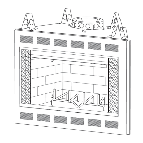
Page 5: Fireplace System Components
EC SERIES INSTALLATION INSTRUCTIONS C. SYSTEM COMPONENTS 1. Fireplace Components Catalog # Description: Fireplace, includes integral grate and hearth protection strips Hearth Extension DM1036 DM1039 DM1042 Original Bifold Glass Doors - Black Finish DM1036B DM1039B DM1042B Original Bifold Glass Doors - Polished Brass Finish DM1036S DM1039S DM1042S... -
Page 6: Fireplace Dimensions
EC SERIES INSTALLATION INSTRUCTIONS Cat. # E/EC36 36 in. [914mm] 41 in. [1041mm] 25-1/4 in. [641mm] 12-5/8 in. [321mm] E/EC39 39 in. [991mm] 44 in. [1118mm] 28-1/4 in. [718mm] 14-1/8 in. [359mm] E/EC42 42 in. [1067mm] 47 in. [1194mm] 31-1/4 in. [794mm] 15-5/8 in. [397mm]... - Page 7 EC SERIES INSTALLATION INSTRUCTIONS 2. Chimney Components The following pictures show only those chimney components which may be safely used with this fireplace. Catalog # Description: CAK4A Chimney Air Kit Insulated Duct/Outside Air Uninsulated Duct/Outside Air SL306 Chimney Section - 6 in. long SL312 Chimney Section - 12 in.
- Page 8 EC SERIES INSTALLATION INSTRUCTIONS Chimney Sections Catalog # SL306 6 in. 4-3/4 in. SL312 12 in. 10-3/4 in. SL330 - Offset/Return SL3 - Chimney Stabilizer SL318 18 in. 16-3/4 in. SL324 24 in. 22-3/4 in. SL336 36 in. 34-3/4 in. SL348 48 in.
- Page 9 EC SERIES INSTALLATION INSTRUCTIONS ST375 Square LDS33 (3 ft x 3 ft) Termination Cap LDS46 (4 ft x 6 ft) Decorative Shroud TS345/TS345P Square Termination Cap TR344 Round Termination Cap TR342 Round Telescoping Termination Cap CT35 Chase Top CAK4A Chimney Air Kit 08/04 17339 Rev L...
-
Page 10: Pre-Installation Preparation
Figures 3 and 4 show two typical installations assuming an outside air kit is being used. Therefore, an allowance must be made for 90-deg bends. Less space is required when ducting goes directly outside without forming elbows. Cat. # E/EC36 42 in. [1067mm] 45 in. [1143mm] E/EC39 45 in. [1143mm] 48 in. [1219mm] E/EC42 48 in. - Page 11 All required clearances to combustibles around the fireplace must be adhered to. Any framing across the top of the fireplace must be above the level of the top standoffs. Chimney sections at any level require a 2 in. minimum air space clearance between the framing and chimney section. Cat. # E/EC36 42 in. [1067mm] E/EC39 45 in. [1143mm] E/EC42 48 in.
-
Page 12: Chimney Requirements
Figure 6. Short stub walls are also acceptable if they are contained within the shaded area. Cat. # E/EC36 36 in. [914mm] 41 in. [1041mm] E/EC39 39 in. [991mm] 44 in. [1118mm] E/EC42 42 in. - Page 13 EC SERIES INSTALLATION INSTRUCTIONS 1. Using Offsets and Returns To bypass any overhead obstructions, the chimney may be offset using a 15-deg or 30-deg offset/return. Perform the following steps to determine the correct chimney component combination for your particular installation. An offset and return may be attached together or a chimney section(s) may be used between an offset and return.
- Page 14 EC SERIES INSTALLATION INSTRUCTIONS 2. Chimney Height Requirements (above roof line) Major building codes specify a minimum chimney height above the roof top. These specifications are summarized in what is known as the Ten Foot Rule. This rule states: “If the horizontal distance from the side of the chimney to the peak of the roof is 10 ft or less, the top of the chimney must be at least 2 ft above the peak of the roof, but never less than 3 ft in overall...
-
Page 15: Installation Of Fireplace
EC SERIES INSTALLATION INSTRUCTIONS F. INSTALLATION OF FIREPLACE WARNING! Before starting, do the following: 1. Wear gloves and safety glasses for protection. 2. Keep hand tools in good condition. Sharpen cutting edges and make sure tool handles are secure. 3. Always maintain the minimum air space required to the enclosure to prevent fire. 1. - Page 16 EC SERIES INSTALLATION INSTRUCTIONS 4. Assemble Chimney Sections Attach either a straight chimney section or an offset to the top of the fireplace (depending on your installation requirement). Chimney sections are locked together by pushing downward until the top section meets the stop bead on the lower section.
- Page 17 EC SERIES INSTALLATION INSTRUCTIONS 8. Secure Chimney System 6. Attic Insulation Shield When offsets and returns are joined to straight pipe An insulation shield should be installed when there sections, they must be locked into position with the is a possibility of insulation coming into contact with screws provided (outer only), using the predrilled holes.
- Page 18 EC SERIES INSTALLATION INSTRUCTIONS 9. Mark the Exit Point of the Roof Locate the point where the chimney will exit the roof by plumbing down to the center of the chimney. Drive a nail up through the roof to mark the center. See Figure 14.
- Page 19 EC SERIES INSTALLATION INSTRUCTIONS 15. Complete the Enclosure Complete the fireplace enclosure, allowing space for outside air ducts and gas piping if desired. Electrical wiring should not come in contact with the fireplace. A minimum clearance of 1/2 in. must be maintained between the fireplace sides and the enclosure as well as the fireplace back and the enclosure.
- Page 20 1/2 in. MICORE CV230, or a material with an equivalent insulation value. Cat. # E/EC36 52 in. [1321mm] 16 in. [406mm] E/EC39 52 in. [1321mm] 16 in. [406mm] E/EC42 66 in. [1676mm] 20 in. [508mm]...
- Page 21 EC SERIES INSTALLATION INSTRUCTIONS 18. Position the Hearth Extension 19. Finishing Material Position and secure the hearth extension over the Do not install combustible materials over the black protective metal strips that have been placed partially face of the fireplace! This poses a safety hazard under the fireplace front.
-
Page 22: Constructing A Chase
EC SERIES INSTALLATION INSTRUCTIONS G. CONSTRUCTING A CHASE 1. Materials A chase is a vertical boxlike enclosure built around the chimney and fireplace. A chase may be constructed for The chase is constructed using framing the fireplace and chimney or for the chimney only. It is most materials much the same as the walls in your commonly constructed on an outside wall. - Page 23 EC SERIES INSTALLATION INSTRUCTIONS 2. Chase Top Construct a chase of desired materials maintaining a minimum 2 in. air space around the chimney. 3. Termination Cap Install the chimney sections up through the chase enclosure. When using a TR344 round termination cap, the uppermost top section of pipe must extend 6 in.
- Page 24 EC SERIES INSTALLATION INSTRUCTIONS For installations utilizing an ST375 square termination cap the last chimney section must not be more than 4-1/2 in. below the chase top. See Figure 24. For installation utilizing a TS345/TS345P Square Termination Cap, the uppermost chimney section must not be more than 3 in.
-
Page 25: Operating Instructions
EC SERIES INSTALLATION INSTRUCTIONS H. OPERATING INSTRUCTIONS Note: Save and pass this instruction manual to subsequent home owners. The informa- tion provided is intended to notify and warn them about making unsafe future modifications such as the addition of shelves or the use of unauthorized parts and repairs. 1. - Page 26 EC SERIES INSTALLATION INSTRUCTIONS 4. Glass Doors 7. Wood Fuel Most efficient fireplace operation using glass doors is FIREWOOD: Your fireplace performance depends on with the doors open. When the doors are open, the the quality of the firewood you use. All seasoned wood, screen must be closed.
- Page 27 EC SERIES INSTALLATION INSTRUCTIONS SEASONING: Seasoned firewood is nothing more than Note: The first three or four fires should be of mod- wood that is cut to size, split and air dried to a moisture erate size to allow the oils and binders to be burned content of around 20%.
- Page 28 EC SERIES INSTALLATION INSTRUCTIONS Flue draft is measured as negative pressure in the If the fire is hard to start and smoke spills out of the chimney. The amount of negative pressure determines fireplace, or you find it difficult to establish and maintain how strong the draft is.
-
Page 29: Maintenance Instructions
EC SERIES INSTALLATION INSTRUCTIONS I. MAINTENANCE INSTRUCTIONS 1. Disposal of Ashes Ashes should be placed in a metal container with a WARNING! tight-fitting lid. The closed container of ashes should A chimney fire can permanently damage your be placed on a noncombustible floor or on the ground, chimney system. - Page 30 EC SERIES INSTALLATION INSTRUCTIONS HOMEOWNER’S NOTES 17339 Rev L 08/04...
-
Page 31: Index
EC SERIES INSTALLATION INSTRUCTIONS INDEX Air Clearance 17, 19 Exhaust Products 10 Negative Air Pressure 27 Air Kit 6, 18 Noncombustible Material 21 Air Kit Handle Location 18 Noncombustible Sealant Material 21 Ashes, Disposal of 29 Fan Kit 5 Attic Insulation Shield 17 Fireplace Enclosure 19 Offsets/Returns 8, 13... -
Page 32: Warranty
HEATILATOR WOODBURNING FIREPLACE LIMITED WARRANTY As part of its 20-YEAR BUYER PROTECTION PROGRAM AS PART OF ITS 20 YEAR BUYER PROTECTION PROGRAM (“PROGRAM”), HEARTH & HOME TECHNOLOGIES INC. (“HHT”) pleased to offer a Limited Warranty and a Replacement Parts Advantage covering specific components of your Heatilator woodburning fireplace system ( the “Fireplace”), installed in the United States of America or Canada.
Need help?
Do you have a question about the EC36 and is the answer not in the manual?
Questions and answers