Heatilator EL36 Series Owner's Manual
Installation and operation
Hide thumbs
Also See for Heatilator EL36 Series:
- Owner's manual (54 pages) ,
- Installation manual (40 pages) ,
- Owner's manual (52 pages)
Table of Contents
Advertisement
Models:
EL36 Series
EL42 Series
Woodburning Fireplace
•
Important operating
a n d m a i n t e n a n c e
instructions included.
WARNING
If the information in these instruc-
tions is not followed exactly, a
fi re may result causing property
damage, personal injury, or death.
• Do not store or use gasoline or other fl am-
mable vapors and liquids in the vicinity of
this or any other appliance.
• Do not overfi re. Overfi ring will void your war-
ranty.
• Comply with all minimum clearances to
combustibles as specifi ed. Failure to comply
may cause house fi re.
Installation and service of this fi replace should be
performed by qualifi ed personnel. Hearth & Home
Technologies suggests NFI certifi ed or factory-
trained professionals, or technicians supervised
by an NFI certifi ed professional.
CAUTION
DO NOT DISCARD THIS MANUAL
•
Read, understand
and follow these
instructions for safe
i n s t a l l a t i o n a n d
operation.
Heatilator • EL36/EL42 • 4044-132 Rev P • 02/07
Owner's Manual
Installation and Operation
•
Leave this manual with
party responsible for
use and operation.
WARNING
HOT! DO NOT TOUCH.
SEVERE BURNS MAY RESULT.
CLOTHING IGNITION MAY RESULT.
Glass and other surfaces are hot
during operation and cool down.
•
Keep children away.
•
CAREFULLY SUPERVISE children in same room
as fi replace.
•
Alert children and adults to hazards of high
temperatures.
•
Keep clothing, furniture, draperies and other
combustibles away.
WARNING
Fire Risk
•
For use with solid wood fuel or decorative
gas appliance only.
•
Do not install unvented gas logs.
1
Advertisement
Table of Contents

Related Manuals for Heatilator Heatilator EL36 Series


Summary of Contents for Heatilator Heatilator EL36 Series
-
Page 1: Woodburning Fireplace
Owner’s Manual Installation and Operation Models: EL36 Series EL42 Series Woodburning Fireplace CAUTION DO NOT DISCARD THIS MANUAL • Read, understand • Leave this manual with • Important operating and follow these party responsible for a n d m a i n t e n a n c e instructions for safe use and operation. - Page 2 Read this manual before installing or operating this fi replace. Please retain this owner’s manual for future reference. Congratulations! Congratulations on selecting a Heatilator wood burning The information contained in this owner’s manual unless noted fireplace. The Heatilator fireplace you have selected is otherwise, applies to all models and gas control systems.
-
Page 3: Table Of Contents
Table of Contents Listing and Code Approvals Finishing A. Appliance Certifi cation ......4 A. Hearth Extension ......26 B. -
Page 4: Listing And Code Approvals
Listing and Code Approvals A. Appliance Certifi cation WARNING This fi replace system has been tested and listed in accor- dance with UL 127 and ULC-S610 standards by Underwrit- Improper installation, adjustment, alteration, service ers Laboratories Inc. for installation and operation in the or maintenance can cause injury or property damage. -
Page 5: Getting Started
Getting Started A. Design and Installation Considerations CAUTION WARNING Check building codes prior to installation. Asphyxiation Risk • Installation MUST comply with local, regional, Negative pressure can cause spillage of state and national codes and regulations. combustion fumes and soot. Fire needs to draft •... - Page 6 Location of the fi replace and chimney will affect performance. As shown in Figure 2.1 the chimney should: • Be installed through the warm airspace enclosed by the building envelope. This helps to produce more draft, especially during lighting and die-down of the fi re. •...
-
Page 7: Typical Fireplace System
C. Typical Fireplace System The Heatilator fi replace system consists of the following: • Fireplace/integral grate/refractory • Chimney termination cap • Chimney system • Hearth extension Optional components include: • Glass doors • Chimney air kit • Outside Air System Additional lateral Termination cap support for chimney... -
Page 8: Tools And Supplies Needed
D. Tools and Supplies Needed E. Inspect Fireplace and Components Before beginning the installation be sure the following tools WARNING and building supplies are available: Reciprocating saw Framing material Fire Risk Pliers High temp caulking material Explosion Risk Inspect fireplace and components for Hammer Gloves damage. -
Page 9: Framing And Clearances
Framing and Clearances WARNING Note: • Illustrations and photos refl ect typical installations Fire Risk and are FOR DESIGN PURPOSES ONLY. Provide adequate clearances. • Illustrations/diagrams are not drawn to scale. • Around air openings • Actual installation/appearance may vary due to •... -
Page 10: Clearances
B. Clearances WARNING Fire Risk • Comply with all minimum clearances to combustibles as specifi ed. • Framing or fi nishing material used on the front of, or in front of, the appliance closer than the minimums listed, must be constructed entirely of noncombustible materials (i.e., steel studs, concrete board, etc.). -
Page 11: Sidewalls/Surrounds
C. Sidewalls/Surrounds Adjacent combustible side walls must be located a minimum of 12 in. (305 mm) from the fi replace opening. See Figure 3.3. If you are using a decorative surround constructed of combustible material, it must be located within the shaded area de- fi... -
Page 12: Construct The Chase
E. Construct the Chase Gas line holes and other openings should be caulked with high temperature caulk or stuffed with unfaced fi berglass in- A chase is a vertical boxlike structure built to enclose the fi re- sulation. If the fi replace is being installed on a cement slab, place and/or its vent system. -
Page 13: Installation Of Fireplace
Installation of Fireplace CAUTION Sharp Edges • Wear protective gloves and safety glasses during installation. Attic insulation shield (not shown) must be 3 ft min. from top of used to keep insulation uppermost chimney away from chimney. A. Install the Outside Air Kit section to air inlet. -
Page 14: Securing The Fireplace
B. Securing the Fireplace CAUTION • Position the Fireplace Risk of Smoke Spillage This fi replace may be placed on either a combustible or noncombustible continuous fl at surface. Follow the in- Outside air inlet must be located to prevent blockage structions for framing in Section 3.D. - Page 15 • Place the Protective Metal Hearth Strips Included with your fi replace you will fi nd two metal hearth strips measuring approximately 26 in. x 4 in. (660 mm x 102 mm). These strips are used to provide added protection where the fi replace and the hearth ex- tension meet.
-
Page 16: Chimney Assembly
Chimney Assembly Termination Cap Chimney must extend beyond combustible roof structure Additional support for Maintain minimum tall chimneys height of chimney above roof Storm Collar Install roof flashing Maintain minimum according to minimum clearances to requirements combustibles as specified Offsets/returns may not exceed Support straps for offsets/ 30°... -
Page 17: Chimney Requirements
A. Chimney Requirements To determine the chimney components needed to complete Vertical distances are measured from the base of the fi re- your particular installation, follow the steps below: place as shown in Figure 5.2. • Determine the total vertical height of the fireplace •... -
Page 18: Using Offsets/Returns
B. Using Offsets/Returns To bypass any overhead obstructions, the chimney may be • Measure how far the chimney needs to be shifted to enable offset using an offset/return. it to avoid the overhead obstacle. See Figure 5.3. Use dimension “A” to determine chimney section required to An offset and return may be attached together or a chimney achieve the needed shift. -
Page 19: Assemble The Chimney Sections
C. Assemble the Chimney Sections Note: The ceiling fi restop MUST be nailed to the bottom of the ceiling joists EXCEPT when the space above is Attach either a straight chimney section or an offset to the uninsulated and the attic insulation shield is not being used top of the fi... -
Page 20: Install The Attic Insulation Shield
E. Install the Attic Insulation Shield Tabs An insulation shield must be installed when there is a pos- sibility of insulation coming into contact with the factory built 14-1/2 in. (368 mm) chimney system. Attic 24 in. • Bend the tabs at the top of the attic insulation shield inward. Insulation (610 mm) Insulation... -
Page 21: Complete The Enclosure
Complete the Enclosure A. Chimney Termination Chimney Termination Requirements (See Figures 6.1 and 6.2) • Must have a cap approved and listed for this fi replace system • Must not be located where it will become plugged by snow or other material •... -
Page 22: Chase Top
Install the Chimney Air Kit (required in Canada): When installing the chimney air kit, follow the instructions provided with this accessory. B. Chase Top A metal chase top is required to seal the top of the chase around the chimney pipe. The top should include a turn- down and drip edge to prevent water from seeping into the chase. -
Page 23: Install The Termination Cap
C. Install the Termination Cap • For installations utilizing an ST375 Square Termination Cap the last chimney section must not be more than Note: To protect against the effect of corrosion on those 4-1/2 in. (114 mm) below the chase top. See Figure 6.7. parts exposed to the weather, the termination cap can be painted with a rust-resistant paint. - Page 24 • For installations utilizing an TCT375 Terra Cotta Cap the last chimney section must be between 7 in. (178 mm) below the chase top and 2 in. (51 mm) above. See Figure 6.9. The last section of pipe must stop between the distances given below.
-
Page 25: Accessories
Accessories A. Gas Log/Lighter Provisions WARNING A certifi ed gas log lighter or decorative gas log set can be installed in this fi replace. Asphyxiation Risk • Maximum input is 100,000 BTU/hr. • Damper must be locked open when gas logs •... -
Page 26: Finishing
Finishing A. Hearth Extension WARNING A hearth extension must be installed with all fi replaces to protect the combustible fl oor in front of the fi replace from Fire Risk both radiant heat and sparks. • Metal hearth strips MUST be installed. This fi... -
Page 27: Hearth Extension
The hearth extension must be covered with non-combustible WARNING materials as illustrated below in Figures 4 and 5. • Non-Combustible Materials Fire Risk Material which will not ignite and burn. Such materials • Metal hearth strips MUST be installed. are those consisting entirely of steel, iron, brick, tile, con- Sparks or embers may ignite fl... - Page 28 Raised Hearth Extension Construction A raised hearth extension that is fl ush with the fi replace opening (Figure 6) or less than 4 in. (102 mm) below the fi replace opening (Figures 4 & 5) requires the fi replace to be installed on a non-combustible surface.
- Page 29 Non-combustible Sealant After completing the framing and applying the facing mate- rials over the framing, a bead of non-combustible sealant must be used to close off any gaps at the top and sides between the fi replace hearth. This will prevent cold air leaks and sparks from falling between the fi...
-
Page 30: Decorative Facing
B. Decorative Facing C. Finishing Material After completing the framing and applying the facing material • Non-Combustible Materials (drywall) over the framing, a bead of non-combustible seal- Material which will not ignite and burn. Such materials ant must be used to close off any gaps at the top and sides are those consisting entirely of steel, iron, brick, tile, con- between the fi... -
Page 31: Mantel
• Combustible Materials E. Sidewalls/Surrounds Materials made of or surfaced with wood, compressed Adjacent combustible side walls must be located a minimum paper, plant fi bers, plastics, or other material that can ig- of 12 in. (305 mm) from the fi replace opening. If you are us- nite and burn, whether fl... -
Page 32: Operating Instructions
Operating Instructions WARNING WARNING HOT! DO NOT TOUCH. Fire Risk SEVERE BURNS MAY RESULT. • Do not operate fireplace before CLOTHING IGNITION MAY RESULT. reading and understanding operating Glass and other surfaces are hot during instructions. operation and cool down. Failure to operate fi... -
Page 33: Outside Air
B. Outside Air E. Firescreen A source of air (oxygen) is required in order for combustion A fi rescreen is always provided to control sparks. It must to take place. Whatever air is consumed by the fi re must be be closed whenever the fi... -
Page 34: Grate
G. Grate Seasoning Seasoned fi rewood is nothing more than wood that is The factory installed integral grate must be used to hold the cut to size, split and air dried to a moisture content of logs from falling out of an open fi replace and to allow air to around 20%. -
Page 35: Starting A Fire
I. Starting a Fire CAUTION Check the fl ue damper to be certain it is in the full open po- sition. Place crumpled or twisted paper under the fi replace Odors and vapors released during initial grate. Loosely arrange kindling or small pieces of wood to operation. -
Page 36: Troubleshooting
Troubleshooting This fi replace will operate correctly only if adequate ventila- fl ue, or some condition is in effect to draw smoke from the tion is provided to allow proper draft to the fi replace system. fi replace into the house. Understanding and differentiating Hearth &... -
Page 37: Diagnostics And Problem Solving
B. Diagnostics and Problem Solving I can’t get a good fi re going. What am I doing wrong? Diagnostic Questions Solutions Possible Causes of Condition Is the damper open? • No draft Open damper. Is there enough paper/starter? • Insuffi cient heat to ignite kindling Use more paper/starter. - Page 38 The fi replace burns the wood too fast. What can I do? Diagnostic Questions Solutions Possible Causes of Condition Do you have glass doors? • Need to slow air intake Add glass doors. What is the condition of the • Extremely dry wood Mix in less seasoned wood after fi...
-
Page 39: Maintenance And Servicing The Fireplace
11 11 Maintenance and Servicing the Fireplace A. Disposal of Ashes B. Chimney Inspection/Cleaning Ashes should be placed in a metal container with a tight-fi t- Inspect the chimney internally for obstructions and construc- ting lid. The closed container of ashes should be placed on tion damage. -
Page 40: Maintenance Task List
CAUTION WARNING Handle glass assembly with care. Asphyxiation Risk When cleaning glass door: Fire Risk • Avoid striking, scratching or slamming Annual inspection by qualified technician glass. recommended. • Do NOT use abrasive cleaners. Check: • Use a hard water deposit glass cleaner on •... -
Page 41: Reference Materials
Reference Materials A. Fireplace Dimensions 7-3/8 in. (187 mm) 21-3/8 in. (543 mm) 7-1/2 in. (191 mm) Outside 39-1/2 in. 21 in. (1003 mm) (533 mm) 21 in. (533 mm) 18-3/4 in. (476 mm) Knockout Knockout 9-1/4 in. 9-1/4 in. 7-1/2 in. -
Page 42: Fireplace Components
B. Fireplace Components Model # Description EL36 EL42 Fireplace, includes integral grate and protective metal hearth strips Hearth Extension DM1036 DM1042 Original Bi-fold Glass Doors - Black Finish DM1036B DM1042B Original Bi-fold Glass Doors - Polished Brass Finish DM1036S DM1042S Original Bi-fold Glass Doors - Stainless Steel Finish GR41 GR40... -
Page 43: Chimney Components
C. Chimney Components The following pictures show only those chimney components which may be safely used with this fi replace. ID4 Insulated Duct CAK4A Chimney Air Kit Insulated Duct/Outside Air 4 in. (102 mm) i.d. Uninsulated Duct/Outside Air 42 in. SL306 Chimney Section - 6 in. - Page 44 Inside Diameter 8 in. (203 mm) 14-1/2 in. Outside (368 mm) Diameter Effective 10-1/2 in. Height (267 mm) Ceiling Firestop 4-3/4 in. (121 mm) Catalog # SL315/SL330 Offset/Return FS338 0-deg. 14-1/2 in. 368 mm FS339 15-deg. 18-3/8 in. 467 mm FS340 30-deg.
- Page 45 20 in. (508 mm) 17 in. 15-3/4 in. (432 mm) (400 mm) 9-3/8 in. (238 mm) TR344 Round Termination Cap 9-1/4 in. (235 mm) TCT375 Terra Cotta Cap 72 in. 36 in. (914 mm) 34-3/4 in. (1829 mm) (883 mm) 10-7/8 in.
- Page 46 European Copper Caps 21 in. (533 mm) 18-1/4 in. (464 mm) 20-3/4 in. (527 mm) 49 in. 41-1/8 in. (1245 mm) (1045 mm) 38-5/8 in. (981 mm) 20 in. 20 in. 24 in. (508 mm) (508 mm) (610 mm) CT3-King CT3-Queen CT3-Bishop 16 in.
-
Page 47: Woodburning Termination Cap
Woodburning Termination Cap TV342 TR342/TR344* TV11/TV11T TS345/T445 TR342/TR344 TR442/TR444* TR11/TR11T* Shroud (Top Vent) TR442/TR444 (* with TR-TVK installed) TR11/TR11T (* with TR-TVK installed) OPEN TOP with solid sides and 3 in. (76 mm) opening at the bottom 28 x 28 in. 32 x 32 in. -
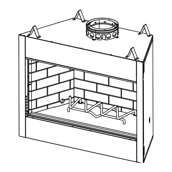
Page 48: Service Parts
D. Service Parts EL36 & EL42 Service Parts Exploded Parts Diagram Beginning Manufacturing Date: January, 2005 ELEMENT Woodburning Fireplace Ending Manufacturing Date: Active 18 - Air Kit 3 - Damper Kit (duct sold separately) (Air Handle) 9 - Screen Assembly Heatilator •... - Page 49 EL36 & EL42 Service Parts Service Parts List Beginning Manufacturing Date: January, 2005 ELEMENT Woodburning Fireplace Ending Manufacturing Date: Active Qty. Description of Part EL36 EL42 req. Starter Section Assembly 22069B 22069B Top Standoff 4044-111 4044-111 Nailing Flange 4044-161 4044-161 Damper Kit 4044-029 4044-029...
- Page 50 This page intentionally left blank. Heatilator • EL36/EL42 • 4044-132 Rev P • 02/07...
-
Page 51: Limited Warranty
E. Limited Warranty HEATILATOR WOODBURNING FIREPLACE Limited Warranty As part of its 20-YEAR BUYER PROTECTION PROGRAM AS PART OF ITS 20 YEAR BUYER PROTECTION PROGRAM (“PROGRAM”), HEARTH & HOME TECHNOLOGIES INC. (“HHT”) is pleased to offer a Limited Warranty and a Replacement Parts Advantage covering specifi c components of your Heatilator® woodburning fi... -
Page 52: Contact Information
F. Contact Information Hearth & Home Technologies Inc. 1915 W. Saunders Street Mt. Pleasant, Iowa 52641 www.heatilator.com Please contact your Heatilator dealer with any questions or concerns. For the number of your nearest Heatilator dealer, please visit www.heatilator.com. – NOTES – CAUTION DO NOT DISCARD THIS MANUAL •...
Need help?
Do you have a question about the Heatilator EL36 Series and is the answer not in the manual?
Questions and answers