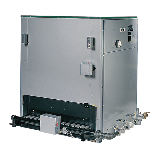
PEERLESS SERIES 211A Installation, Operation & Maintenance Manual
Gas boilers-steam
Hide thumbs
Also See for SERIES 211A:
- Installation, operation & maintenance manual (59 pages) ,
- Installation, operation & maintenance manual (59 pages)

Subscribe to Our Youtube Channel
Related Manuals for PEERLESS SERIES 211A


Summary of Contents for PEERLESS SERIES 211A
- Page 1 211A Boilers - Steam Installation, Operation Maintenance Manual PEEI_LESS CAST IRON BOILERS...
- Page 2 (IlyUI(I[)I(,, CAST IRON BOILENS 1_1('(1_" ( I)IL'.,Illl /)('('l!(,.%N l [_'(lll'l (t?!lt)(l!l{ ( ll!l{[)_('!<" Ip(lll(l?lll] II!tOl'lll(l[[(lll Peerless Heater Company • 231 North Walnut Street * Boyertown, 19512 1021 • 610-367-2153 • www.peerless-heater.com FA[_ 211A (9/02 pnrlh (I ,fl U S A...
- Page 3 American Society of Mechanical Engineers Safety Code for Controls and Safety Devices for Automatically Fired Boi/ers, ANSI/ASME CSD-1. PEERLESS CAST IRON BOILERS PEERLESS HEATER COMPANY 231 NORTH WALNUT STREET • BOYERTOWN, PA 19512-1021 • PHONE 610-367-2153 www.peerless-heater.com THE PREFERRED...
-
Page 4: Table Of Contents
TABLE OF CONTENTS 8. INSTALL CONTROLS TRIM 1. PREPARE BOILER LOCATION ACCESSIBILITY CLEARANCES ........INSTALL SAFETY VALVES ........COMBUSTIBLE CONSTRUCTION CLEARANCES..INSTALL BLOWDOWN VALVES ......AIR FOR COMBUSTION AND VENTILATION ..... 3 INSTALL LOW WATER CUTOUT(S) ......CHIMNEY OR VENT ............ INSTALL PRESSURE CONTROLS ...... - Page 5 These categories 2. You can also use this survey to locate system problems mean, in the judgment of Peerless Heater Company: which will have to be corrected. To obtain copies of the Steam Installation Survey, contact...
-
Page 6: Prepare The Boiler Location
PREPARE THE BOILER LOCATION Vent,typcal _ 6',, ] P,p,ng, T ypcal "-_ if''_ (:-'--_ Front View Figure Clearance Requirements The boiler room must never be under negative pressure. • If exhaust fans or other equipment can cause a negative pressure in the boiler room, the air openings I The following recommendations... - Page 7 • Provide two openings: one starting no closer than 3 inches nor further than 1 :::xll 12 inches from the ceiling ..one starting no closer than 3 inches nor frlrther than TWO AIR OPENINGS: 12 inches horn the floor MhlinqLim •...
- Page 8 Recommendedsizingfor chimney and connectors is all combustion products. If the vent system does not based on maximum 6 foot connector length and provide enough draft, combustion products will spill into maximum one 90 degree elbow. the building from the draft hood relief opening. If spillage of combustion products occurs, check the vent system, the combustion...
- Page 9 Table Boiler Foundation Layout Boiler Boiler Base Jackel Foundation Provid_ a good, levd foundation for the boi]el t_,.n Model Length Length Length minimum dim_nsKJlm givun m Tahlf ] ThP fluulh _ ,--! _,t/stt, t3] RIU_t h( _ qUltdhlL' 2!1A 22 I 2 28 1 _ 40 1/8"...
- Page 10 ASSEMBLE THE BASE 2. Op_zn cl_t_' numb*'l t£_mov_, the End P_llc]_ ,,zd toward t}t_ IllOUI]t a _tippor_ ChL_lllle] C]ip I_al ,:_1_ n panel as shown in Figure 9 using _"-20 x L,," round humid Co][_'cl the! cr_t_!s _onlaU/ing the 13as_ Assemb[_; palts (able 2 machine screws and _'...
- Page 11 3. Attach the Front Panel and Back Panel (Figure 9) to the For 211 A-09 through 211 A-46 Only: Left Hand End Panel using 5/16" -18 x 1" cap screws Attach a Front Panel Support Bracket to each Front and hex head nuts provided. Panel as shown in Figure 11.
- Page 12 Overall Length _r ..• Assembly I_• Assembly I_• Assembly I_• Assembly I_• Assembly Ib• Assembly I_• Assembly Model Overall Number Length 211A 04 2434 211A O5 30 3/8" 211A 06 211A 07 41 5/8" 211A 47 1 4' 27/8 211A-09 211A 1 58 1'2'...
- Page 13 :1II:1/ill: I:f:T_'_ © © © Manifold Weldment GG-4084 thru GG-4084-46 Imperial #68F 1/4" NPT x 3/8" O.D. Tube Straight Connector Orifix_e4A0d3Pter\\ _ Mounting Clamp GG-3052thru GG-3052-3 3/8" x 3/8" x 1/4" Tee I 1/4" Street Elbow 3/8" Pipe Cap_ Pipe Cap 1/4"...
- Page 14 Table Pilot Burner Locations-Numbered Right to Left (See Figure PROPANE GAS ONLY NATURAL ONLY Total Pilot Burner Locations Number Pilot Burnei Locations Model Number of Positions Numbered Right to Left Number Pilots Positions Numbered Right [o Left) Electronic Pilots Standing Pilots Burners Electronic Pilots...
- Page 15 TAPPINGS, EACH END SECTION 3/4" npt Tapping 1 1/2" nptTapping, Back, Blowdown 1/2" npt Tapping, Upper H 3" npt Tapping, Pop Safety Valve(s) and 1" npt Tapping, Upper Upper Equalizer for Special Float 1/2" npt Tapping, Lower Controls (157, etc) 3/4"...
-
Page 16: Place The Boiler Sections
PLACE THE BOILER SECTIONS 1 Check the level of the Boiler Base using a spirit level• Make sure the base is level and that the base panels aligned within plus or minus I'16". 2 Check the area around the Flow Ports (Figure 14). Use solvent and a clean cloth to thorougly clean the flat... - Page 17 Place Tapped Intermediate Sections Boiler Model Number at Positions (Numbered Left to Right) 211A ]S 211A-19 211A 2{I 211A-21 211A _7 211A-23 & 16 211A 24 9,17 211A 25 7, 13, 19 Spirit Level 211A 26 7, 1:_ 20 211A-27 7, 12, 17, 22 211A 28 5 11,17...
-
Page 18: Install The Flue Collector
INSTALL THE FLUE COLLECTOR 1. ColDct the l:lu_' Coikzctor cartons. The Flue Cdlactot LongHook Bolt, sections are ]abal_,d on tile part and on the carton See HiTempRope AngleBracket, Table 4 for the items needed. GG-50O5 6G-5003 2. Install Hi Tamp Rope for each collector section as shown in Figure 18. - Page 19 Table Flue Collector Section Location (From Left to Right Facing Front of Boiler) - Crates Crate 14 = Part number GG-5000 Crate = Part number GG-500O-1 Crate = Part number GG-5000-2 Boiler Position Position ! Position Position Position Position Position Position Position Model...
-
Page 20: Pipe The Boiler
Boiler Riser. (See valve, nipple and cap for skimming the boiler in the Peerless Heater Company's "Steam installation Survey" tee as shown in the piping drawings. for discussion). Locating the Steam Supply between the risers will cause water carryover to the system. - Page 21 Steam Second Equalizer Supply 1A-16 and Larger i ] Steam _Supply Return Connection 2" Skim Connection 2' Skim 211A-04 TO 211A-07 SINGLE END RISER Offset Header Required to Prevent Damage _, Return to Boiler From Expansion of Header 211A-08 TO 211A-17 Second quaL:;ger RISERS...
- Page 22 Boiler Riser Piping enters TOP of main Figure 24 shows typica{ piping for multiple boiler Gravity on Counterflow Return systems. Figure 25 shows typical piping multiple boiler Pumped Return systems• System 2. Provide separate feed lines for multiple boiler pumped return systems•...
- Page 23 Steam Stop Valve Supply Pipe All Headers Minimum 24" Above Boiler Water Line Stop Valve Stop Valve Return Figure Piping Multiple Boilers, Typical, Gravity Return Systems Steam stop Supply Valve Pipe All Headers Minimum 24" Above Boiler Water Line ":5 F/T Drip To recover Trap...
- Page 24 INSTALL THE JACKET 8 DRAFT HOOD Inselt Front Panel (GG 60231 flange (on light side of panet) under the edge of the Right Front Corner Panel. Place the left edge of the Front Panel over the offset 1. Collect the Jacket cartons and Draft Hood cartons...
- Page 25 • Install a Panel Support Angle ontheinside topofthe Apply the last Top Panel in the same way. Place its right Upper RearPanel ( SeeFigure 27).Use#I0 x _/" hand edge over the Top Right End Panel. Secure with sheet m etal s crews. x Vi' sheet metal screws.
- Page 26 Top Panel (GG-6024) Right End Panel (GG-6019) Top Left End Panel (GG-6020) Upper Left End Panel (GG-6032 (GG-6023) Front Panel Lower Right Front Panel Corner Panel (GG-6022) (GG-6015) Corner Panel Support Bracket Front Jacket Panel (GG-6029) Support Bracket (GG-2069) Left End Corner Cleanout Cover Panel (GG-6016)
- Page 27 • ,.::1 • '_._ Table Jacket Draft Hood Carton Contents - See Figure 27 for Placement of Jacket Sections Ca_on Contents Sub-Assembly Part Number Quantity ' Cleanout Cover Plates GG-6004 GG-6015 Jacket Corner Pane!, Right Front Jack_'t Cumin Pan_'! Leit Front G(J 6016 GG-6017 Jacket...
- Page 28 31 33 35 37 39 21 23 25 27 Number of Ca_ons Boiler Model 2iiA-O4 211_ 1 L_ 2! 1A 06 211A-07 211A-08 211A-09 211A-10 211A-1! A' ! Figure Jacket Assembly Sequence - Carton Numbers Locations...
- Page 29 Table Draft Hood Section Placement (from Left to Right Facing Front of Boiler) ModeIB°iler li Position , Position2 Position3 Position4 Position5 Position6 Position7 Position8 Position9 211A 04 211A 05 = 211A-06 [ 211A-07 ! 2uA-os L 211A709 ii 211A-10 " !i 211A-!! i 211A-12 , 211A 13...
- Page 30 CONNECT GAS PIPING Connect Pilot Line to the, Pilot Cock Assembly supplied with the Gas Control Train 1 The Gas Control Train(s) supplied with this boiler: Connect tubing to each pilot s Has been factory assembled and tested for tightness Connect electronic pilots to the Pilot Gas Valves.
- Page 31 2 Diaphragm Gas Valves Pipe diaphragm gas valve bleed lines to outside Size the piping as required by the National Fuel Gas atmosphere unless the boiler is equipped with Code. ANSI Z223 1,_FPA54 or as required by local standing pilot. On standing pilot boilers, pipe the codes...
- Page 32 Table Capacity of Gas Supply Pipe in Cubic Feet Per Hour of Natural Gas for 0.3 inch Drop 21/2 " 3" 4" 6" Pipe Length 1 V4" 1 1/2" (Feet) Pipe Pipe Pipe Pipe Pipe Pipe Pipe 1050 1600 3050 4800 8500 17500...
- Page 33 INSTALL CONTROLS AND TRIM 1 Pipe the Pop Salety Valve(s) in the 3"" tappings located Mount the float type Low Water Cutout and Gauge Glass on the right or left end sections Make sure the relief valve in the tappings provided in the front of either end section.
- Page 34 Option 1 Option 2 3/4" x 3" Nipple 3/4" X 3/4" X 1/4" Reducing 3/4" Cross 3/4" x 4" Nipple 3/4" x 5" Nipple 3/4" Plug 1/2" x 6" Brass Nipple 3/4" x 1/2" Hex Bushing Steam Gauge 3/4" x 1/4" Hex Bushing Pressuretrols 1/4"...
- Page 35 • -*_1_1JflhV_l t_lli_ ... l.-| 8 1/2" Burner Cut-Off Level Water Line 4" 1 3/4" f ..2"- 1/2'_ 5" Conduit Connection Figure 33: Standard Float Type Control, Model 67PE2 Figure Optional Feeder/Low Water Cutout, Model 47-2 - Used Only on Models 211A-04 through 211A-08...
- Page 36 Burner Cutoff Level (Mark on Casting) Normal Water Line 12 5/16" 12" Install 1" Blowoff Valve Boiler Foundation SUGGESTED FII-rlNGS LIST 1" Cross 1" x 6" Nipple 1" Ground Joint Union 1" x 8" Nipple 1" Plug 1" x 8 1/4" Nipple 1"...
- Page 37 Normal Water Line Control Center Line • 3/4" Feeder Closing Level (Mark on Casting) 12 7/8" Burner Cut4Off Level is 1 1/2" Below Center Line on 51-2 and 51-S-2 Controls (2 3/4" Below Normal Water Line) 40 1/2" _' 4 1/8" -_ 8 1/8"...
-
Page 38: Wire The Boiler
WIRE THE BOILER 1 All wiring must be done in accordance with local codes. th_ conlrol Mount transforma on the ]umlion National Electrical Code other controlling shown in Figure 37 agencies or governing bodies Mount a iunction box near each Gas Control Train connection of conduit... - Page 39 120 V'dO hz 120v/60hz Neutral High Limit Pf _ss[Jre Control High Gas Pressure Switch (H C645B) Transformer Probe Type Water Through 211A 18) Additional 120V,24V (Modeis211A = :_1_i I CtltolJt Hydrolevel Limit Switches Model 650P Shown Flame Rollout 1OOva (When Req'd) Switch (When Req'd)
- Page 40 120V 60hz [L2) 120 V'60 hz Neutral High LimO Pressure Control Hi!tb Gas Pressure (ModeisSWitch (H21C645B)IA ' ':_} {I'_I) "_ Transformer Probe Type Water 120V/24V Cutout Hydrolevel Tbrough 211A 18) Adddional Flame Rollout Limit Switches Model 650P Shown 40 va Switch (When Req'd) (When Req'd)
-
Page 41: Starting The Boiler
STARTING THE BOILER Turn down the Operatm 9 Pn_ssure Control to stop fl_e call for heat. Water and Steam Piping to allow the control Wait b0 seconds to reset before proceeding with the next step The Boiler must have been hydrostatically tested. - Page 42 boiler wateL producing an unstable water line and water 1] mole adjustment to the rate is needed it nlust be done by changing the, burner gas ()rifices carryover to the system. The Minimum input rak, listed on tl_e nameplate Cleaning the boiler requires the dpplies to boilers wifll...
- Page 43 1 1. LIGHTING INSTRUCTIONS - TYPICAL 1 These instructions apply only to typical standard control 1. Open main line power clisconnect switch to boiler. systems (HSP System only). Use the Lighting Instructions 2. Close Main and Pilot gas shut off valves. supplied with the boiler to be sure they apply to the actual control system used 2.
- Page 44 OPERATION MAINTENANCE • ignHio;i control should close the m,_lin gil> store allow valves wilhin _ seconds after tire pilot goe_ _tl_ combustible flammable • After i5 seconds, the control will lock out materials near boiler. • Open the Pilot manual gas shut-off valve Substantial...
- Page 45 F, Test the operation of all limit conh his float conhols igntion components as described in Pa_t A. *Placing I. Beforethestart Boiler in Operation", of this Chaptel of each heating seasom inspect and make all necessary adjustments to insure proper boiler n]aintenance nperation...
- Page 46 113. TROUBLESHOOTING - SERVICE TIPS PROBLEM POSSIBLE CAUSE SUGGESTED REMEDY Defective Thermocouple Replace Redirect Air Movement or Ehmlnate Heavy Draft Blowing across Prlot ReD ace Ordlce Plugged Pdot Onhce Check Manual Pilot Valve Pilot Outage Check Main Gas Shut Off Valve No Gas Check Manual Meter...
- Page 47 POSSIBLE CAUSE PROBLEM SUGGESTED REMEDY Manual Valve Closed at Gas Train aden Valve Main Gas Valve Opens Manual Va ve Closed at Metel _I tH] valve But No Gas Flows Test Firing Valve Closec if Provided Ooen Valve S_gs 5iedrll l_ i_lll(l c_r _1_31 _317o Ci;rrt,L:[...
- Page 48 BOILER RATINGS f:lrDIMENSIONS Table: Boiler Rating Information Propane Gas (2500 Btu/Cu Boiler IBR Net Ratings IBR Net Ratings Model Input Output = Steam Input Output Steam Natural Gas Ratings Number Steam Water Steam P=pmg r Sr_el_11 [ Steam Piping Factor Sq Ft Factor 211A 04...
- Page 49 TAPPING SCHEDULE (211A 19 and Larger,Two Gas Control Trains)) End Supply Riser Taps, 6" each End Section 1211A 04 thru 211A-18,Sngle Gas Control Train) Return Taps, 6" Each End 3" Tap, Top, Each End Section 3% ° "AA- 3B - EE "...
- Page 50 BOILER DIMENSIONAL DATA (All Dimensions In Inches) Flue Boiler Length_ Width ! Boiler Intermediate Riser Center Lines- 3" Tappings- Used In Addition to Two End Risers Flue Connectio, Ce,te( Lines Model Dimenslo,s ' SBgton i ..Connections _ • C ! Lengt ih D iT ;_ L P ;...
- Page 51 1 5. REPAIR PARTS - SERIES 21 1A • REPAIR PARTS ARE AVAIIABI_E FROM YOUR INSTALLER OR BY CONTACTING PEERLESS HEATER COMPANY, BOYERTOWN. PA 19512-t021 • PLEASE INCLUDE BOILER MODEL NUMBER AND SERIAL NUMBER WHEN ORDERING PARTS • SEE FIGURE 42. BOILER ASSEMBLY AND FIGURE 43, BASE ASSEMBLY o.sc°,.,o°...
- Page 52 PART ITEM DESCRIPTION ADDITIONAL INFORMATION NUMBER 143/4" Wide GG-2053 203/8" Wide GG 2053-2 Base Front Panel Cover Piate 26" Wide GG-2053 31 '8 Wide GG 2053-6 371/4" Wide GG-2053 143/4" Wide GG-2053-1 203/8 " Wide GG-2053-3 Base Back Panel Cover Plate 26"...
- Page 53 5.'] =1 ;1_=[.']v.lIEIr_,l Figure Boiler Assembly...
- Page 54 ®...
- Page 56 OWNER: This boiler should inspected annually Qualified Service Agency. gama PEERLESS CAST IRON BOILERS PEERLESS HEATER COMPANY 231 NORTH WALNUT STREET • BOYERTOWN, PA 19512-1021 • PHONE 610-367-2153 www.peerless-heater.com PREFERRED HEATING CHOICE @2002 Peerless Heater...
Need help?
Do you have a question about the SERIES 211A and is the answer not in the manual?
Questions and answers