PEERLESS Series 211A Installation, Operation & Maintenance Manual
Gas boilers-water
Hide thumbs
Also See for Series 211A:
- Installation, operation & maintenance manual (57 pages) ,
- Installation, operation & maintenance manual (59 pages)

Related Manuals for PEERLESS Series 211A


Summary of Contents for PEERLESS Series 211A
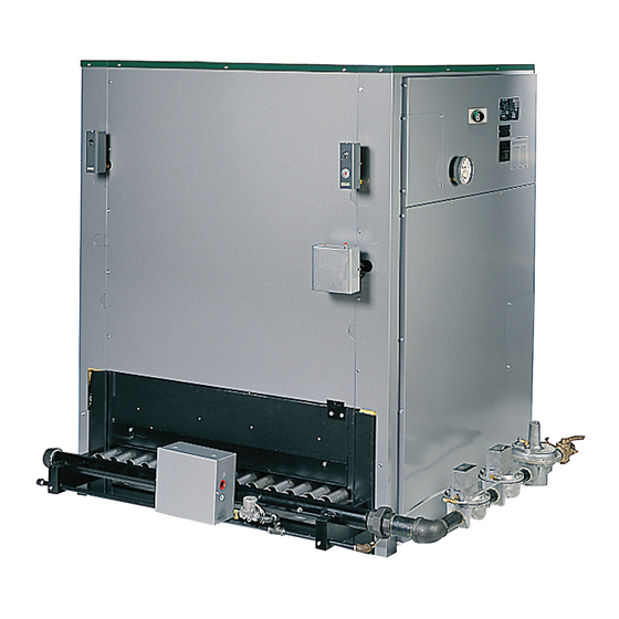
- Page 1 Series 211A Boilers – Water I n s t a l l a t i o n , O p e r a t i o n & M a i n t e n a n c e M a n u a l...
-
Page 2: Table Of Contents
G. APPLY LOWER END PANELS ...28 14. BOILER RATINGS & DIMENSIONS H. APPLY PLATES AND LABELS ...28 15. REPAIR PARTS - SERIES 211A... -
Page 3: Using This Manual
USING THIS MANUAL USING THIS MANUAL DANGER A. FOLLOW THE PIPING GUIDELINES 1. We have provided suggested piping diagrams which Indicates a condition or hazard which will cause will cover most applications of this boiler. severe personal injury, death or major property damage. -
Page 4: Preinstallation
PREINSTALLATION 1. PREINSTALLATION NOTICE The equipment shall be installed with those installation requirements of the authority having jurisdiction or, in the absence of such requirements, to the current edition of the National Fuel Gas Code , ANSI Z223.1/NFPA 54 and/or CAN/CGA B149 Installation Codes. - Page 5 See Figure 1.3 for an known, the minimum required volume of indoor illustration of this arrangement. air for appliances other than fan assisted and for the Series 211A Boiler shall be determined as follows: ⎛ I other 21 ft ⎜...
- Page 6 PREINSTALLATION i. Where communicating directly or through vertical ducts with the outdoors each opening shall have a minimum free area of 1 in 4000 Btu/hr (22 cm per 4000 W) of total input rating for all equipment in the space. See Figure 1.4 for openings directly communicating with the outdoors or Figure 1.5 for openings connected by ducts to the...
-
Page 7: Chimney Or Vent
PREINSTALLATION 5. Combination Indoor and Outdoor Combustion Air: If iii. Nonmotorized dampers shall be fixed in the the required volume of indoor air exceeds the open position. available indoor air volume, outdoor air openings or ducts may be used to supplement the available b. - Page 8 PREINSTALLATION • 3. Chimney/Vent Operation: The vent system must be The vent connector must be single wall steel sized and installed to provide the draft needed to or Type B double wall vent pipe. The vent remove all combustion products. If the vent system connector must be Type B double wall if it is does not provide enough draft, combustion products located in or passes through cold areas.
-
Page 9: Boiler Setting
PREINSTALLATION f. After it has been determined that each appliance WATER QUALITY AND MAKE-UP remaining connected to the common venting system properly vents when tested as outlined 1. Check the system to make sure there are no leaks or above, return doors, windows, exhaust fans, overfilling problems which might cause excessive fireplace dampers and any other gas-burning make-up water to be added. - Page 10 PREINSTALLATION Table 1.1: Boiler Foundation Layout Boiler Base Length Jacket Length Foundation Length Boiler Model inches inches inches 211A-04 22-1/2 28-1/8 40-1/8 1019 211A-05 28-1/8 33-3/4 45-3/4 1162 211A-06 33-3/4 39-3/8 1000 51-3/8 1305 211A-07 39-3/8 1000 1143 1448 211A-08 1143 50-5/8 1286...
-
Page 11: Assemble The Base
ASSEMBLE THE BASE 2. ASSEMBLE THE BASE 2. Open crate number 2. Remove the End Panels and A. BASE ASSEMBLY mount a Support Channel Clip toward the rear on each panel as shown in Figure 2.2 using 1/4"-20 x 1. Collect the crates containing the Base Assembly 1/2"... -
Page 12: Install The Pilot Burners
ASSEMBLE THE BASE 3. Attach the Front Panel and Back Panel (Figure 2.2) to 5. For 211A-09 through 211A-46 Only: the Left Hand End Panel using 5/16"-18 x 1" (25 mm) a. Attach a Front Panel Support Bracket to each long cap screws and hex head nuts provided. - Page 13 ASSEMBLE THE BASE Table 2.1: Base Front and Back Panel Crates Overall Length Model Number feet/inches 211A-04 — — — — — — 24-3/4" 211A-05 — — — — — — 30-3/8" 211A-06 — — — — — — 36" 211A-07 —...
- Page 14 ASSEMBLE THE BASE Figure 2.5: Typical Gas Manifold and Pilot Line Assembly 4. Place only the Burners with pilots mounted in the 5. Cut and fit the 1/4" aluminum tubing provided from locations given in Table 2.2. Install each Burner by the pilot gas shut-off device(s) to the pilot burners.
- Page 15 ASSEMBLE THE BASE Table 2.2: Pilot Burner Locations – Numbered Right to Left (See Figure 2.1) Natural Gas Only Propane Gas Only Total Model Number of Number Pilot Burner Locations Pilot Burner Locations Number Pilots (Positions Numbered Right to Left) (Positions Numbered Right to Left) Burners Electronic Pilots...
-
Page 16: Place The Boiler Sections
PLACE THE BOILER SECTIONS 3. PLACE THE BOILER SECTIONS A. PREPARATION 1. Check the level of the Boiler Base using a spirit level. Make sure the base is level and that the base panels are aligned within plus or minus 1/16" (2 mm). 2. - Page 17 PLACE THE BOILER SECTIONS Figure 3.3: Assembling Sections on Base...
-
Page 18: Hydrostatic Test The Boiler
PLACE THE BOILER SECTIONS Place Tapped Intermediate Boiler Model Number Sections at Positions (Numbered Left to Right) 211A-29 10, 20 211A-30 11, 21 211A-31 10, 22 211A-32 11, 23 211A-33 13, 25 211A-34 9, 17, 26 211A-35 9, 18, 27 211A-36 13, 21, 29 211A-37... -
Page 19: Install The Flue Collector
INSTALL THE FLUE COLLECTOR 4. INSTALL THE FLUE COLLECTOR 1. Collect the Flue Collector cartons. The Flue Collector sections are labeled on the part and on the carton. See Table 4.1 for the items needed. 2. Install Hi Temp Rope for each collector section as shown in Figure 4.1. - Page 20 INSTALL THE FLUE COLLECTOR Table 4.1: Flue Collector Section Location (From Left to Right Facing Front of Boiler) – Crates Crates 14 = Part number GG-5000 Crate 14A = Part number GG-5000-1 Crate 14B = Part number GG-5000-2 Boiler Position Position Position Position...
-
Page 21: Pipe The Boiler
PIPE THE BOILER 5. PIPE THE BOILER A. PREPARATION 1. Make sure the boiler has been pressure tested as outlined in Section 3, “Place the Boiler Sections” in this manual. 2. The Supply and Return piping can be installed before installing the jacket. Use nipples long enough to extend through the jacket. - Page 22 PIPE THE BOILER Table 5.1: Boiler Supply and Return Location & Sizing & Recommended Header Sizing Flow Rate, Intermediate Flow Rate, Intermediate 20°F/11°C Supply Supply & Header 20°F/11°C Supply Supply & Header Boiler Boiler Output Rise & Return Size, Output Rise &...
-
Page 23: Low System Temperature
PIPE THE BOILER temperature rise) are acceptable provided the return temperature to the boiler is at least 130°F (54°C) to prevent condensation of flue gases. 3. Do not reduce the number or size of supply and return connections given in Table 5.1. These are required to control the flow velocities in the boiler and maintain uniform distribution. - Page 24 PIPE THE BOILER to room temperature, such as on night set-back primary/secondary systems with a large primary systems or energy management systems, cold circuit temperature drop. See Figure 5.4 for start-ups will occur often. These systems require multiple boilers. a Variable Low Temperature piping and control arrangement, described below.
-
Page 25: Chilled Water Systems
PIPE THE BOILER excessive cycling. To protect the boiler and MULTIPLE BOILER INSTALLATIONS provide proper operation, install a temperature control valve and boiler circuit pump piped off of 1. Multiple boilers should be piped in a secondary loop. the system as a secondary loop. See Figure 5.5 Each boiler should be provided with its own pump for single boilers and Figure 5.8 for multiple and piped off of the secondary loop header. - Page 26 PIPE THE BOILER Figure 5.6: Piping to Isolate Boiler from Chilled Medium on Chiller Systems...
- Page 27 PIPE THE BOILER Figure 5.7: Multiple Boiler Piping, System Return Temperature Above 54°C (130°F)
- Page 28 PIPE THE BOILER Figure 5.8: Piping for Variable Low Temperature Systems, Multiple Boilers...
-
Page 29: Install The Jacket & Draft Hood
INSTALL THE JACKET & DRAFT HOOD 6. INSTALL THE JACKET & DRAFT HOOD 2. Open Jacket Intermediate Section carton, 12A, B, C, A. PREPARE THE PARTS D or E, per Table 6.1. Remove necessary knockouts from panels. 1. Collect the Jacket cartons and Draft Hood cartons (numbers 12 and 13). -
Page 30: Apply Jacket Top Panels
INSTALL THE JACKET & DRAFT HOOD • Slip the right edge of the last Front Panel under 3. Slide the left hand offset flange of the first Top Panel the Right Front Corner Panel. Line up the holes under the Top Left End Panel. Place the front flange and secure with #10 x 1/2"... - Page 31 INSTALL THE JACKET & DRAFT HOOD Top Panel (GG-6024) Top Right End Panel (GG-6019) Top Left End Panel (GG-6020) Upper Left End Front Panel Panel (GG-6032) (GG-6023) Lower End Right Front Panel Corner Panel (GG-6022) (GG-6015) Corner Panel Support Bracket Front Jacket Panel (GG-6029) Support Bracket...
- Page 32 INSTALL THE JACKET & DRAFT HOOD Table 6.1: Jacket and Draft Hood Carton Contents – See Figure 6.2 for Placement of Jacket Sections Carton Contents Sub-Assembly Part Number Quantity Cleanout Cover Plates GG-6004 Jacket Corner Panel, Right Front GG-6015 Jacket Corner Panel, Left Front GG-6016 Jacket Corner Panel, Right Rear GG-6017...
- Page 33 INSTALL THE JACKET & DRAFT HOOD Figure 6.3: Jacket Assembly Sequence - Carton Numbers and Locations...
- Page 34 INSTALL THE JACKET & DRAFT HOOD Table 6.2: Draft Hood Section Placement (from Left to Right Facing Front of Boiler) Boiler Position Position Position Position Position Position Position Position Position Model Number 211A-04 — — — — — — — —...
-
Page 35: Connect Gas Piping
CONNECT GAS PIPING 7. CONNECT GAS PIPING 3. Connect tubing to each pilot. A. INSTALL GAS TRAIN a. Connect electronic pilots to the Pilot Gas Valves. 1. The Gas Control Train(s) supplied with this boiler: b. Connect standing pilots (when supplied – see •... -
Page 36: Install Gas Supply Piping
CONNECT GAS PIPING c. When piping bleed lines to outside, terminate the 2. The standard gas train is designed for a maximum tubing downward to prevent water from entering pressure of 1/2 psig (14 inches water column/3.5 the tubing, and protect the tubing termination kPa). - Page 37 CONNECT GAS PIPING Table 7.1: Capacity of Gas Supply Pipe in Cubic Feet (Cubic Meters) Per Hour of Natural Gas for 0.3 inch (75 Pa) Drop. Pipe Length 1-1/4" Pipe 1-1/2" Pipe 2" Pipe 2-1/2" Pipe 3" Pipe 4" Pipe 6"...
-
Page 38: Install Controls And Trim
INSTALL CONTROLS AND TRIM 8. INSTALL CONTROLS AND TRIM 2. Pipe the valve discharge to a floor drain if available or A. INSTALL SAFETY RELIEF VALVE(S) apply a nipple and cap to close off when not in use. 1. Pipe the Safety Relief Valve(s) in the 3" tapping(s) located on the top of the right and left end sections. -
Page 39: Wire The Boiler
WIRE THE BOILER 9. WIRE THE BOILER A. CONNECT SUPPLY WIRING B. PREPARE REMAINING CONTROLS 1. All wiring must be done in accordance with local 1. Mount the control transformer on the junction box as codes, the National Electrical Code ANSI/NFPA70 shown in Figure 9.1. - Page 40 WIRE THE BOILER 120V/60hz 120 V/60 hz Neutral High Limit Temperature High Gas Pressure Control (M/R) Switch (C6097B) (Models 211A-13 Transformer Probe Type Low Water Through 211A-18) Additional 120V/24V Cutoff - Hydrolevel Limit Switches 100 va Model 650P Shown (When Req'd) Float Type Low Water Cutoff...
- Page 41 WIRE THE BOILER 120V/60hz 120 V/60 hz Neutral High Limit Temperature High Gas Pressure Control (M/R) Switch (C6097B) (Models 211A-13 Transformer Probe Type Low Water Through 211A-18) Additional 120V/24V Cutoff - Hydrolevel Limit Switches 40 va Model 650P Shown (When Req'd) Float Type Low Water Cutoff...
-
Page 42: Starting The Boiler
STARTING THE BOILER 10. STARTING THE BOILER CAUTION A. CHECK THE PIPING The boiler gaskets will be damaged by petroleum or 1. Water Piping its derivatives. a. The Boiler must have been hydrostatically tested. Do not use petroleum based compounds in the boiler, b. -
Page 43: Check Main Burner System
STARTING THE BOILER d. The main gas valves will then open and the main Meter). Divide by “T” – the time in seconds of burners should ignite. the meter reading. Rate, Watts = F x H e. Turn down the Operating Temperature Control to stop the call for heat. -
Page 44: Lighting Instructions - Typical
LIGHTING INSTRUCTIONS – TYPICAL 11. LIGHTING INSTRUCTIONS – TYPICAL A. TO LIGHT THE BOILER B. TO SHUT DOWN THE BOILER 1. These instructions apply only to typical standard 1. Open main line power disconnect switch to boiler. control systems (HSP System only). Use the Lighting 2. -
Page 45: Operation & Maintenance
OPERATIONS & MAINTENANCE 12. OPERATION & MAINTENANCE WARNING Product Safety Information Refractory Ceramic Fiber Product This appliance contains materials made from refractory ceramic fibers (RCF). Airborne RCF, when inhaled, have been classified by the International Agency for Research on Cancer (IARC), as a possible carcinogen to humans. -
Page 46: Placing Boiler In Operation
OPERATIONS & MAINTENANCE • WARNING Open the Pilot manual shut-off valve and re- start the boiler per the Lighting Instructions. (Standing pilots will have to be manually re- Do not store or allow combustible or flammable lit per the Lighting Instructions.) materials near the boiler. -
Page 47: To Shut Down The Boiler
OPERATIONS & MAINTENANCE c. Remove side cleanout panels. B. TO SHUT DOWN THE BOILER d. Brush the boiler tube spaces both horizontally 1. Open main line power disconnect switch to boiler. (through cleanout openings on ends) and vertically (from top of boiler). 2. -
Page 48: Troubleshooting - Service Tips
TROUBLESHOOTING – SERVICE TIPS 13. TROUBLESHOOTING – SERVICE TIPS Problem Possible Cause Suggested Remedy Defective Thermocouple Replace Heavy Draft Blowing across Pilot Redirect Air Movement or Eliminate Plugged Pilot Orifice Replace Orifice Pilot Outage Check Manual Pilot Valve Check Main Gas Shut-Off Valve No Gas Check Manual Meter Valve Consult Gas Company... - Page 49 TROUBLESHOOTING – SERVICE TIPS Problem Possible Cause Suggested Remedy Air Adjustment Screws Turned in Too Far Adjust Screws Out Low Gas Pressure in Manifold Adjust Main Gas Pressure Regulator (Insufficient Air Injection) or Check Line Pressure Burner Ports Partially Closed Replace Burners or Clean Ports (Rust, Dirt, Lint, etc) Burner(s) Burning with Yellow Flame...
-
Page 50: Boiler Ratings & Dimensions
BOILER RATINGS & DIMENSIONS 14. BOILER RATINGS & DIMENSIONS Table 14.1: Boiler Rating Information Natural Gas Ratings LP Gas (2500 Btu/cu ft.; 93,000 kJ/m Boiler IBR Net Ratings IBR Net Ratings Model Input Output Water Input Output Water Number 211A-04 211A-05 211A-06 1,050... - Page 51 BOILER RATINGS & DIMENSIONS...
- Page 52 BOILER RATINGS & DIMENSIONS...
- Page 53 BOILER RATINGS & DIMENSIONS...
-
Page 54: Repair Parts - Series 211A
REPAIR PARTS – SERIES 211A 15. REPAIR PARTS – SERIES 211A Repair parts are available from your installer or by contacting PB Heat, LLC, New Berlinville, PA. Use the Figures and Tables on Pages 52-55 to assist in ordering parts. - Page 55 REPAIR PARTS – SERIES 211A Item Stock Description Part Selection Information Code 14-3/4" (375 mm) Wide 90316 20-3/8" (518 mm) Wide 90318 Base Front Panel Cover Plate 26" (660 mm) Wide 90320 31-5/8" (803 mm) Wide 90322 7-1/4" (9463) Wide 90324 14-3/4"...
- Page 56 REPAIR PARTS – SERIES 211A Figure 15.1: Boiler Assembly...
- Page 57 REPAIR PARTS – SERIES 211A Figure 15.2: Base Assembly...
- Page 58 NOTES...
- Page 59 Series 211A Boilers – Water I n s t a l l a t i o n , O p e r a t i o n & M a i n t e n a n c e M a n u a l TO T H E I N S TA L L E R : This manual is the property of the owner and must be affixed near the boiler for future reference.
Need help?
Do you have a question about the Series 211A and is the answer not in the manual?
Questions and answers