Icom IC-F1710 Instruction Manual
Mobile
Hide thumbs
Also See for IC-F1710:
- Instruction manual (36 pages) ,
- Operating manual (12 pages) ,
- Service manual (48 pages)

Related Manuals for Icom IC-F1710


Summary of Contents for Icom IC-F1710
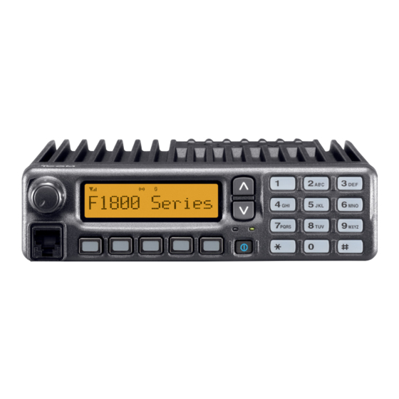
- Page 1 INSTRUCTION MANUAL VHF MOBILE TRANSCEIVER iF1710 iF1810 UHF MOBILE TRANSCEIVER iF2710 iF2810 Above photo shows the IC-F1810 or IC-F2810.
-
Page 2: Important
Consult your Icom dealer or system operator for details concerning your transceivers programming. Icom, Icom Inc. and the Icom logo are registered trademarks of Icom Incor- porated (Japan) in Japan, the United states, the United Kingdom, Germany, France, Spain, Russia and/or other countries. -
Page 3: Precautions
Icom transceiver. Icom is not responsible for the destruction or damage to an CAUTION! NEVER expose the transceiver to rain, Icom transceiver in the event the Icom transceiver is used snow or any liquids. -
Page 4: Table Of Contents
TABLE OF CONTENTS IMPORTANT ................i n Printer connection ............23 EXPLICIT DEFINITIONS ............i n Digital ANI ..............23 PRECAUTIONS ..............ii n Auto emergency transmission ........23 TABLE OF CONTENTS ............iii n Stun function ..............24 n BIIS indication ............24 1 PANEL DESCRIPTION ..........1–7 n Priority A channel selection ........24 n Front panel ..............1 n Horn output ..............24... -
Page 5: Panel Description
BUSY INDICATOR e DIAL or UP/DOWN KEYS Lights green while receiving a signal, or when the squelch • IC-F1710, F2710: DIAL is open. Rotate to select an operating channel, etc. • IC-F1810, F2810: UP/DOWN Keys Push to select an operating channel, etc. -
Page 6: Function Display
PANEL DESCRIPTION n Function display y POWER SWITCH [POWER] Push to turn the power ON and OFF. • The following functions are available at power ON as options: - Automatic scan start - Password prompt - Set mode 1 3 6 . 1 N a r u TRANSMIT INDICATOR Lights red while transmitting. -
Page 7: Programmable Function Keys
[DOWN], [P0], [P1], [P2], [P3] and [P4] programmable func- ceived, according to the pre-programming. tion keys. Consult your Icom dealer or system operator for details con- u CALL CODE MEMORY INDICATOR cerning your transceivers programming. Appears when the call code memory is selected. - Page 8 PANEL DESCRIPTION ZONE KEY ➥ Push and hold this key for 1 sec. to indicate the scan Push this key, then select the desired zone using [CH Up]/ group, then select the desired group using [CH Up]/ [CH Down]. [CH Down]. What is “zone”?—The desired channels are assigned into SCAN ADD/DEL (TAG) KEY a zone according to the intended use for grouping.
- Page 9 PANEL DESCRIPTION PUBLIC ADDRESS KEY HIGH/LOW KEY While in the hailer mode, push this key for the audio output via Push to select the transmit output power temporarily or per- the hailer amplifier. Ask your dealer for details. manently, depending on the pre-setting. While in the normal mode, the audio output via the cable can •...
- Page 10 PANEL DESCRIPTION RE-DIAL KEY TX CODE ENTER KEY Push to transmit the last-transmitted DTMF code. Push to enter the ID code edit mode directly, for both 5- tone and BIIS. Then set the desired digit using [CH Up]/ CALL KEYS [CH Down] or 10-keypad*.
-
Page 11: Panel Description
PANEL DESCRIPTION COMPANDER KEY I STATUS UP/DOWN KEYS (BIIS operation only) Push to toggle the compander function ON and OFF. ➥ While in the standby condition, push (or rotate)* to display The compander function reduces noise components from the the transmit status indication and select a status number. transmitted audio to provide clear communication. -
Page 12: Basic Operation
BASIC OPERATION n Turning power ON n Channel selection q Push [ ] to turn the power ON. Several types of channel selections are available. Methods w If the transceiver is programmed for a start up password, may differ according to your system set up. input the digit codes as directed by your dealer. -
Page 13: Call Procedure
BASIC OPERATION n Call procedure n Receiving and transmitting When your system employs tone signaling (excluding CTCSS Receiving: and DTCS), the call procedure may be necessary prior to voice q Push [ ] to turn the power ON. transmission. The tone signalling employed may be a selective w Push [CH Up] or [CH Down], or rotate [CH Up/Down] to calling system which allows you to call specific station(s) only select a channel, in sequence. -
Page 14: Transmitting Notes
BASIC OPERATION ï Transmitting notes ï TX code channel selection • Transmit inhibit function If the transceiver has [TX Code CH Select] assigned to it, The transceiver has several inhibit functions which restrict the indication can be toggled between the operating channel transmission under the following conditions: number (or name) and TX code channel number (or name). -
Page 15: Tx Code Number Edit
BASIC OPERATION ï TX code number edit USING [TX CODE ENTER] KEY: q Select the desired TX code channel via [TX Code CH If the transceiver has [TX Code CH Select] or [TX Code Enter] Select]+[CH Up] or [CH Down], [TX Code CH Up], [TX assigned to it, TX code contents can be edited within the al- Code CH Down] or [TX Code CH Up/Down]. -
Page 16: Scrambler Function
BASIC OPERATION ï DTMF transmission n Scrambler function If the transceiver has [DTMF Autodial] assigned to it, the auto- matic DTMF transmission function is available. Up to 8 DTMF The voice scrambler function provides private communication channels are available. between stations. The frequency inversion type is equipped to all versions, moreover, the optional Rolling or Non-rolling type TO SELECT A TX CODE: can be available. -
Page 17: User Set Mode
BASIC OPERATION n User set mode e Push [ ] again to exit set mode. User set mode can be accessed with ‘Power ON’ function. In this case, all set mode items are available. User set mode allows you to set seldom-changed settings and you can “customize”... -
Page 18: Biis Operation
BIIS OPERATION n Default setting n Receiving a call ï Individual call The following functions are assigned to each programmable key as the default. However, the assigned function can be q When an individual call is received; changed by your dealer. Ask your dealer for details. •... -
Page 19: Group Call
BIIS OPERATION ï Group call ï Displaying the received call record — Queue indication q When a group call is received; • Beeps sound. The transceiver memorizes the calling station ID in the mem- • “ ” appears and the mute is released. ory. -
Page 20: Transmitting A Call
BIIS OPERATION n Transmitting a call ï Calling back from the queue channel A total of 3 ways for code selection are available—selecting q While in the standby condition, push [P1] (Digital) for 1 sec. the call code from memory, entering the call code from the to enter the queue memory channel selection mode. - Page 21 BIIS OPERATION ï Direct code entry q While in the standby condition, push [P3] (TX Code Enter) u Push [PTT] to transmit; release to receive. to enter the TX code edit mode. i Push [P4] (Moni(Audi)) to send the ‘Clear down’ signal. •...
-
Page 22: Receiving A Message
BIIS OPERATION n Receiving a message ï Receiving an SDM (Short Data Message) ï Receiving a status message q When an SDM is received; q When a status message is received; • Beeps sound. • Beeps sound. • The calling station ID (or text) and the SDM is displayed alter- •... - Page 23 BIIS OPERATION ï Received message selection The transceiver memorizes the received message in the r Push [P1] (Digital) for 1 sec. again to return to the standby memory. Up to 6 messages for status and SDM, or 95 charac- condition. ter SDM’s can be memorized.
-
Page 24: Transmitting A Status
BIIS OPERATION n Transmitting a status ï Transmitting a status ï General q While in the standby condition, push [P1] (Digital), then The status message can be selected with the programmed push [Up] or [Down], or rotate [DIAL] to select the desired text, and the message text is also displayed on the function station/group code. -
Page 25: Transmitting An Sdm (Short Data Message)
BIIS OPERATION n Transmitting an SDM (Short Data Message) ï General ï Transmitting an SDM The short data message, SDM, can be sent to an individual q While in the standby condition, push [P1] (Digital), then station or group stations. Also, 8 SDM memory channels are push [Up] or [Down] or rotate [DIAL] to select the desired available and the messages can be edited via PC program- station/group code. - Page 26 BIIS OPERATION ï Programming an SDM memory • Available characters (IC-F1810 or IC-F2810 only) Characters q During standby condition, push [P1] (Digital) twice, then ! ? ' " , ; : _ ( ) < > [ ] push [Up] or [Down] to select the desired SDM to be ed- 1 (space) # * / + - = &...
-
Page 27: Position Data Transmission
BIIS OPERATION n Position data transmission n Digital ANI When the optional cable and a GPS receiver is connected to The own ID can be transmitted each time the PTT is pushed the transceiver, the position (longitude and latitude) data can (log-in) or released (log-off) during individual or group call be transmitted automatically. -
Page 28: Stun Function
BIIS OPERATION n Stun function n Priority A channel selection When the specified ID, set as a killer ID, is received, the stun When one of the following operations is performed, the trans- function is activated. ceiver selects the Priority A channel automatically. When the killer ID is received, the transceiver switches to the Priority A is selected when;... -
Page 29: Connection And Maintenance
SPEAKER JACK Supplied speaker SP-22 placement. Connect a 4–8 ø (IC-F1810 or IC-F2810 only. external speaker. IC-F1710 and IC-F2710 has a built-in speaker.) R WARNING! NEVER remove the fuse-holder from the DC power cable. r MICROPHONE HANGER Connect supplied microphone hanger to the vehicle’s... -
Page 30: Supplied Accessories
CONNECTION AND MAINTENANCE n Supplied Accessories • Function name stickers Microphone Microphone hanger Microphone There are no names on the programmable function keys since and screw set hanger cable the functions can be freely assigned to these keys. Attach the supplied function name stickers as below to the appropriate keys for easy recognition of that key’s assigned function. -
Page 31: Mounting The Transceiver
CONNECTION AND MAINTENANCE n Mounting the transceiver n Optional UT-109 or UT-110 installation The universal mounting bracket supplied with your transceiver allows overhead mounting. Install the optional UT-109 or UT-110 unit as follows: • Mount the transceiver securely with the 4 supplied screws to a thick surface which can support more than 1.5 kg. -
Page 32: Optional Opc-617 Installation
CONNECTION AND MAINTENANCE n Optional OPC-617 installation n Optional UT-109 or UT-110 installation (Continued) r Install the unit as shown in the diagram below. Install the OPC-617 as shown below. FRONT FRONT OPC-617 t Replace the bottom cover and screws, then re-connect the Cut off the bushing as in the DC power cable. -
Page 33: Antenna
CONNECTION AND MAINTENANCE n Antenna n Options • RMK-2 + OPC-609 A key element in the performance of any communication sys- separation kit separation cable tem is an antenna. Contact your dealer about antennas and Allows you to install the transceiver main unit separately the best places to mount them. -
Page 34: Doc
EN 300 219 (March 2001) Signature vi) EN 300 113-2 v1.1.1 (March 2001) CE Versions of the IC-F1710/F1810/F2710/F2810 This warning symbol indicates that this equipment which display the “CE” symbol on the serial num- operates in non-harmonised frequency bands and/... - Page 35 EN 300 086-2 v1.1.1 (March 2001) v) EN 300 219 (March 2001) Signature vi) EN 300 113-2 v1.1.1 (March 2001) About e-marking: Detailed installation notes for Icom mobile transceivers to be fitted into vehicles are available. Please contact your Icom dealer or distributor.
- Page 36 < Intended Country of Use > A-6407H-1EU-e Printed in Japan © 2004–2009 Icom Inc. 1-1-32 Kamiminami, Hirano-ku, Osaka 547-0003, Japan Printed on recycled paper with soy ink.
Need help?
Do you have a question about the IC-F1710 and is the answer not in the manual?
Questions and answers