Icom IC-F1000 Series Operating Manual
Vhf and uhf
Hide thumbs
Also See for IC-F1000 Series:
- Service manual (39 pages) ,
- Instructions (4 pages) ,
- Operating manual (26 pages)

Subscribe to Our Youtube Channel
Related Manuals for Icom IC-F1000 Series


Summary of Contents for Icom IC-F1000 Series
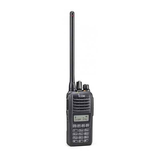
- Page 1 OPERATING GUIDE VHF TRANSCEIVERS iF1000 Series UHF TRANSCEIVERS iF2000 Series The photo shows the UHF transceivers. ▲ Non-display type ▲ Simple type ▲ 10-key type...
- Page 2 VHF TRANSCEIVERS • IC-F2000, IC-F2000S, and IC-F2000T UHF TRANSCEIVERS Icom, Icom Inc. and the Icom logo are registered trademarks of Icom Incor- porated (Japan) in Japan, the United States, the United Kingdom, Germany, France, Spain, Russia and/or other countries. All other products or brands are registered trademarks or trademarks of their...
-
Page 3: Table Of Contents
TABLE OF CONTENTS IMPORTANT ................i 3 MDC 1200 SYSTEM OPERATION ......20–22 TABLE OF CONTENTS ............ii ■ MDC 1200 system operation ........20 ■ Receiving a call ............20 1 PANEL DESCRIPTION ..........1–9 ■ Transmitting a call ............22 ■ Front, top and side panels ..........1 ■... -
Page 4: Panel Description
PANEL DESCRIPTION ■ Front, top and side panels There are three types of transceivers in the IC-F1000 and IC-F2000 series. ROTARY SELECTOR IC-F1000/F2000: Non-display type ANTENNA IC-F1000S/F2000S: Simple type [display + 4 keys (P0–P3)] CONNECTOR VOLUME IC-F1000T/F2000T: 10-key type [display + 4 keys + 10-key pad] CONTROL [VOL] [Emer] INDICATOR... - Page 5 PANEL DESCRIPTION r SPEAKER-MICROPHONE JACK o LED INDICATOR Connect optional equipment. Lights red while transmitting. ➥ ➥ Lights green while receiving a signal, or when the ➥ NOTE: After turning OFF the transceiver, connect or dis- squelch is open. connect the optional equipment. Lights or blinks orange when the matched 2-Tone or ➥...
-
Page 6: Function Display
PANEL DESCRIPTION ■ Function display r COMPANDER ICON ➥ Appears when the Compander function is ON. t SCRAMBLER ICON Appears when the Voice Scrambler function is ON. ➥ y BELL ICON Appears or blinks when a matched 2-Tone or 5-Tone is ➥... -
Page 7: Led Indicator
F/S Sca n PANEL DESCRIPTION L ow BATT1 ■ LED indicator L ow BATT2 The LED indicator indicates the status of various parameters of TX L ow BATT1 the transceiver as follows: • Receiving (Reference: R=Red, G=Green, O=Orange) TX L ow B ATT2 •... -
Page 8: Programmable Function Keys
< for the Simple type and 10-key type transceivers > Push to start and cancel a scan. Consult your Icom dealer or system operator for details con- ➥ cerning your transceiver’s programming. - Page 9 PANEL DESCRIPTION PRIORITY A CHANNEL, PRIORITY B CHANNEL LOCK Push to select the Priority A or Priority B channel. < for the Non-display type transceivers > ➥ Hold down this key to lock all programmable keys except ➥ PRIORITY A CHANNEL (REWRITE), the followings: PRIORITY B CHANNEL (REWRITE) [Moni], [Lock], [Emer], [Surveillance], [Siren], [Lone...
- Page 10 PANEL DESCRIPTION C.Tone CH ENT CALL // only for the Simple type and 10-key type transceivers // Push to transmit a 2-Tone or 5-Tone in the operating chan- ➥ Push to enter the continuous tone selection mode. Select nel. ➥ the tone frequency or DTCS code using [CH Up] or [CH Down].
- Page 11 PANEL DESCRIPTION SURVEILLANCE TX CODE CH SELECT < for the Non-display type transceivers > // only for the Simple type and 10-key type transceivers // [TX Code CH Select] to enter the TX code channel Hold down to turn ON the Surveillance function. Push ➥...
-
Page 12: Panel Description
PANEL DESCRIPTION TX CODE CH UP/DOWN USER SET MODE // only for the PMR model (for the Simple type and // only for the Simple type and 10-key type transceivers // 10-key type transceivers) // Hold down to enter the User Set mode. ➥... -
Page 13: Basic Operation
BASIC OPERATION ■ Selecting a channel ■ Receiving and transmitting CAUTION: There are several types of channel selections. Methods may differ, depending on the presetting. Consult your dealer for Attach an antenna before transmitting. details. Transmitting without an antenna may damage the trans- ceiver. -
Page 14: D Transmitting Notes
BASIC OPERATION Transmitting notes Receiving a Stun, Kill and Revive call • Transmit inhibit function The dispatcher can send a 2-Tone or 5-Tone that will stun, kill The transceiver has several inhibit functions which restrict or revive your transceiver. transmission under the following conditions: When the Stun call is received, beeps sound*, and you can- not receive or transmit. -
Page 15: Emergency Call
BASIC OPERATION ■ Emergency Call When pushing [Emergency] for the set time period*, the NOTE: transceiver transmits an emergency signal once, or repeat- Depending on the presetting, the following functions are automatically activated. Ask your dealer for details. edly, on the specified emergency channel. •... -
Page 16: Lone Worker Emergency Call
BASIC OPERATION ■ Lone Worker Emergency Call ■ Man Down Emergency Call When the Lone Worker function is ON, and if no operation This function may or may not be available, depending on the occurs for a set time period*, the transceiver automatical- presetting. -
Page 17: User Set Mode
BASIC OPERATION ■ User set mode Backlight The User Set mode enables you to change various settings. • ON: Always lit You can “customize” the transceiver operation to suit your • AUT: Lit for 5 seconds when pushing preferences and operating style. any key except [PTT]. - Page 18 BASIC OPERATION SQL (Squelch) Level Signal Moni • 0: SQL Open • ON: Signaling beeps sound. • 2: SQL Threshold • OFF: No signaling beeps sound. • 9: SQL Tight AF Min Level Lone Worker (Minimum audio output level) • ON: If no operation occurs for a set time period, the transceiver au- •...
-
Page 19: Setting The Beep Function
BASIC OPERATION ■ Setting the Beep function These instructions are for the non-display type transceivers. [ROTARY SELECTOR] The Beep function can be turned ON or OFF. When it is OFF, the channel announcement is also turned OFF. [VOL] NOTE: You should turn ON the Beep function when you set the Beep level, the Ringer level, the microphone gain, and the squelch level. -
Page 20: Setting The Beep Level
BASIC OPERATION ■ Setting the Beep level NOTE: These instructions are for the non-display type transceivers. The Beep level is adjustable between 1 and 5, or 1 (linked) and This operation may not be selectable, depending on the presetting, Ask your dealer for details. 5 (linked). -
Page 21: Setting The Ringer Level
BASIC OPERATION ■ Setting the Ringer level NOTE: These instructions are for the non-display type transceivers. The Ringer level can be adjusted between 1 and 5, or 1 This operation may not be selectable, depending on the presetting. Ask your dealer for details. (Linked) and 5 (Linked). -
Page 22: Setting The Microphone Gain
BASIC OPERATION ■ Setting the microphone gain ■ Setting the squelch level These instructions are for the non-display type transceivers. These instructions are for the non-display type transceivers. Adjust the microphone gain. The squelch circuit mutes the received audio signal, de- pending on the signal strength. -
Page 23: Mdc 1200 System Operation
The calling station ID (or alias) is displayed. An additional feature of the MDC 1200 system included in Icom transceivers is called aliasing. Each transceiver on the < Calling station ID > system has a unique ID number. Aliasing is a substitute for this ID number and you can give an alphanumeric name for each station ID. - Page 24 MDC 1200 SYSTEM OPERATION D Receiving an Emergency Call D Receiving a Stun or Revive Call q When an emergency call is received: If a Stun call is received that matches your station ID, the • Beeps sound. transceiver will display a stun text and you can not receive or EMG EMG”...
-
Page 25: Transmitting A Call
MDC 1200 SYSTEM OPERATION ■ Transmitting a call Transmitting a PTT ID Transmitting an Emergency Call You can notify another person of your station ID or alias. When holding down [Emergency] for a set time period, the emergency signal is transmitted once or repeatedly* on the [PTT] to make a call. - Page 26 A-7122-3EX-q 1-1-32 Kamiminami, Hirano-ku, Osaka 547-0003, Japan © 2014 Icom Inc.
Need help?
Do you have a question about the IC-F1000 Series and is the answer not in the manual?
Questions and answers