Icom IC-F1710 Instruction Manual
Vhf, uhf mobile transceiver
Hide thumbs
Also See for IC-F1710:
- Instruction manual (36 pages) ,
- Operating manual (12 pages) ,
- Service manual (48 pages)

Subscribe to Our Youtube Channel
Related Manuals for Icom IC-F1710


Summary of Contents for Icom IC-F1710
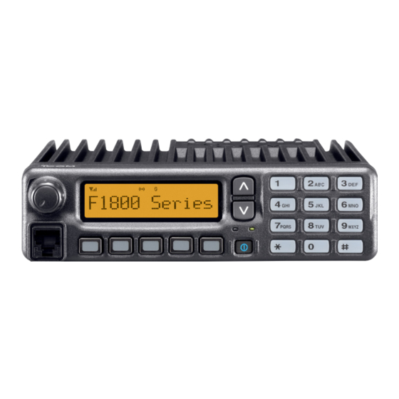
- Page 1 INSTRUCTION MANUAL VHF MOBILE TRANSCEIVER iF1710 iF1810 UHF MOBILE TRANSCEIVER iF2710 iF2810 Above photo shows the IC-F1810 or IC-F2810.
-
Page 2: Important
READ ALL INSTRUCTIONS pletely before using the transceiver. SAVE THIS INSTRUCTION MANUAL — instruction manual contains important operating instructions for the IC-F1710, IC-F1810, IC-F2710 and IC-F2810 VHF/ UHF MOBILE TRANSCEIVERS. EXPLICIT DEFINITIONS WORD Personal injury, fire hazard or electric shock RWARNING may occur. - Page 3 AVOID operating the transceiver without running the vehi- cle’s engine. The vehicle’s battery will quickly run out if the transceiver transmits while the vehicle’s engine OFF. AVOID placing the transceiver in excessively dusty envi- ronments. AVOID placing the transceiver against walls. This will obstruct heat dissipation.
-
Page 4: Table Of Contents
TABLE OF CONTENTS IMPORTANT ... i EXPLICIT DEFINITIONS ... i PRECAUTION ... i TABLE OF CONTENTS ... iii 1 PANEL DESCRIPTION ... 1–7 I Front panel ... 1 I Function display ... 2 I Programmable function keys ... 3 2 BASIC OPERATION ... 8–13 I Turning power ON ... -
Page 5: Panel Description
Displays a variety of information, such as an operating channel number/name, 5-tone code, DTMF numbers and audible condition, etc. e DIAL or UP/DOWN KEYS • IC-F1710, F2710: DIAL Rotate to select an operating channel, etc. • IC-F1810, F2810: UP/DOWN Keys Push to select an operating channel, etc. -
Page 6: I Function Display
PANEL DESCRIPTION y POWER SWITCH [POWER] Push to turn the power ON and OFF. • The following functions are available at power ON as options: - Automatic scan start - Password prompt - Set mode u TRANSMIT INDICATOR Lights red while transmitting. i DEALER-PROGRAMMABLE KEYS Desired functions can be programmed independently by your dealer. -
Page 7: I Programmable Function Keys
The following functions can be assigned to [DIAL]*, [UP], [DOWN], [P0], [P1], [P2], [P3] and [P4] programmable func- tion keys. Consult your Icom dealer or system operator for details con- cerning your transceivers programming. If the programmable function names are bracketed in the fol- lowing explanations, the specific key is used to activate the... - Page 8 PANEL DESCRIPTION ZONE KEY Push this key, then select the desired zone using [CH Up]/ [CH Down]. What is “zone”?—The desired channels are assigned into a zone according to the intended use for grouping. For example, ‘Staff A’ and ‘Staff B’ are assigned into a “Business”...
- Page 9 PUBLIC ADDRESS KEY While in the hailer mode, push this key for the audio output via the hailer amplifier. Ask your dealer for details. While in the normal mode, the audio output via the cable can be controlled from the transceiver separately from [VOL] con- trol knob when an optional OPC-617 ACC CABLE •...
- Page 10 PANEL DESCRIPTION RE-DIAL KEY Push to transmit the last-transmitted DTMF code. CALL KEYS Push to transmit a 5-tone/BIIS ID code. • Call transmission is necessary before calling another station depending on your signalling system. • [Call A] and/or [Call B] may be available when your system employs selective ‘Individual/Group’...
- Page 11 COMPANDER KEY Push to toggle the compander function ON and OFF. The compander function reduces noise components from the transmitted audio to provide clear communication. HOOK SCAN KEY When the hook on scan function is turned ON, push this key to stop scanning temporarily.
-
Page 12: Basic Operation
BASIC OPERATION I Turning power ON q Push [ ] to turn the power ON. w If the transceiver is programmed for a start up password, input the digit codes as directed by your dealer. • 10-keypad* can be used for password input. *IC-F1810 or IC-F2810 only •... -
Page 13: I Call Procedure
I Call procedure When your system employs tone signaling (excluding CTCSS and DTCS), the call procedure may be necessary prior to voice transmission. The tone signalling employed may be a selec- tive calling system which allows you to call specific station(s) only and prevent unwanted stations from contacting you. -
Page 14: D Transmitting Notes
BASIC OPERATION D Transmitting notes • Transmit inhibit function The transceiver has several inhibit functions which restrict transmission under the following conditions: - The channel is in mute condition (‘Inaudible’ condition; “ ” does not appear.) - The channel is busy. - Un-matched (or matched) CTCSS is received. -
Page 15: D Tx Code Number Edit
D TX code number edit If the transceiver has [TX Code CH Select] or [TX Code Enter] assigned to it, TX code contents can be edited within the allowable digits. USING [TX CODE CH SELECT] KEY: q Push [TX Code CH Select] to enter the TX code channel selection mode. -
Page 16: D Dtmf Transmission
BASIC OPERATION D DTMF transmission If the transceiver has [DTMF Autodial] assigned to it, the auto- matic DTMF transmission function is available. Up to 8 DTMF channels are available. TO SELECT A TX CODE: q Push [DTMF Autodial]— a DTMF channel appears. w Push [CH Up] or [CH Down], or rotate [CH Up/Down] to select the desired DTMF channel. -
Page 17: I User Set Mode
I User set mode User set mode is accessed with [User Set Mode] and allows you to set seldom-changed settings. In this case you can “customize” the transceiver operation to suit your preferences and operating style. Entering the user set mode: q While pushing and holding [P1] and [P2], push [ the power ON. -
Page 18: Biis Operation
BIIS OPERATION I Default setting The following functions are assigned to each programmable key as the default. However, the assigned function can be changed by your dealer. Ask your dealer for details. NOTE: [TX Code Enter] must be assigned to a key. [P0];... -
Page 19: D Group Call
D D Group call q When a group call is received; • Beeps sound. • “ ” appears and the mute is released. • The programmed text message (e.g.“ tion ID (or text) is displayed when the indication mode is 2 lines. •... -
Page 20: I Transmitting A Call
BIIS OPERATION I Transmitting a call A total of 3 ways for code selection are available—selecting the call code from memory, entering the call code from the keypad and calling back from the queue channel record. D D Using call memory q While in the standby condition, push [P1] (Digital) to enter the call code memory channel selection mode. -
Page 21: D Direct Code Entry
D D Direct code entry q While in the standby condition, push [P3] (TX Code Enter) to enter the TX code edit mode. • Code digit for editing blinks. 0 5 0 0 w Push [P3] (TX Code Enter) to select the desired digit to be edited. -
Page 22: I Receiving A Message
BIIS OPERATION I Receiving a message D D Receiving a status message q When a status message is received; • Beeps sound. • The calling station ID (or text) and the status message is dis- played alternately when the indication mode is 1 line, depending on the setting. -
Page 23: D Received Message Selection
D D Received message selection The transceiver memorizes the received message in the memory. Up to 6 messages for status and SDM, or 95 char- acter SDM’s can be memorized. The oldest message is erased when the 7th message is received. However, once the transceiver is powered OFF, all messages are cleared. -
Page 24: I Transmitting A Status
BIIS OPERATION I Transmitting a status D D General The status message can be selected with the programmed text, and the message text is also displayed on the function display of the called station. Up to 24 status types (1 to 24) are available, and the status messages 22 and 24 have designated meanings. -
Page 25: I Transmitting An Sdm (Short Data Message)
I Transmitting an SDM D D General The short data message, SDM, can be sent to an individual station or group stations. Also, 8 SDM memory channels are available and the messages can be edited via PC program- ming. (Short Data Message) D D Transmitting an SDM q While in the standby condition, push [P1] (Digital), then push [Up] or [Down] or rotate [DIAL] to select the desired... -
Page 26: D Programming An Sdm Memory
BIIS OPERATION D D Programming an SDM memory (IC-F1810 or IC-F2810 only) q During standby condition, push [P1] (Digital) twice, then push [Up] or [Down] to select the desired SDM to be edit- w Push [M] or [#] to enter the message editing condition. •... -
Page 27: I Position Data Transmission
I Position data transmission When the optional cable and a GPS receiver is connected to the transceiver, the position (longitude and latitude) data can be transmitted automatically. Ask your dealer or system operator for connection details. The position data is transmitted when; •... -
Page 28: I Stun Function
BIIS OPERATION I Stun function When the specified ID, set as a killer ID, is received, the stun function is activated. When the killer ID is received, the transceiver switches to the password required condition. Entering of the password via the keypad is necessary to operate the transceiver again in this case. -
Page 29: Connection And Maintenance
NOTE: Use the terminals as shown below for the cable connections. Crimp Solder Supplied speaker SP-22 (IC-F1810 or IC-F2810 only. IC-F1710 and IC-F2710 has a built-in speaker.) r MICROPHONE HANGER Connect the supplied mi- crophone hanger to the vehicle’s ground for mi-... -
Page 30: I Supplied Accessories
CONNECTION AND MAINTENANCE I Supplied Accessories Microphone Microphone hanger and screw set DC power cable Speaker* Key cap Mounting bracket Flat washers Spring washers Nuts *IC-F1810/F2810 only • Function name stickers Microphone There are no names on the programmable function keys hanger cable since the functions can be freely assigned to these keys. -
Page 31: I Mounting The Transceiver
I Mounting the transceiver The universal mounting bracket supplied with your transceiv- er allows overhead mounting. • Mount the transceiver securely with the 4 supplied screws to a thick surface which can support more than 1.5 kg. Flat washer Spring washer When using self-tapping screws CONNECTION AND MAINTENANCE... -
Page 32: I Optional Ut-109 Or Ut-110 Installation
CONNECTION AND MAINTENANCE I Optional UT-109 or UT-110 installation q Turn the power OFF, then disconnect the DC power cable. w Unscrew the 4 cover screws, then remove the bottom cover. e Cut the pattern on the PCB at the TX mic circuit (MIC) and RX AF circuit (AF OUT), then solder CP37 as shown below. -
Page 33: I Antenna
I Antenna A key element in the performance of any communication sys- tem is an antenna. Contact your dealer about antennas and the best places to mount them. I Fuse replacement A fuse is installed in the supplied DC power cable. If a fuse blows or the transceiver stops functioning, track down the source of the problem if possible, and replace the damaged fuse with a new rated one. -
Page 34: Doc
CE Versions of the IC-F1710/F1810/F2710/ F2810 which display the “CE” symbol on the serial number seal, comply with the essential requirements of the European Radio and Telecommunication 1999/5/EC. We Icom Inc. Japan 1-1-32, Kamiminami, Hirano-ku Osaka 547-0003, Japan Declare on our sole responsibility that this equipment complies with the... - Page 35 EN 300 086-2 v1.1.1 (March 2001) v) EN 300 219 (March 2001) vi) EN 300 113-2 v1.1.1 (March 2001) About e-marking: Detailed installation notes for Icom mobile transceivers to be fitted into vehicles are available. Please contact your Icom dealer or distributor.
- Page 36 < Intended Country of Use > A-6407H-1EU-w Printed in Japan © 2004–2006 Icom Inc. Printed on recycled paper with soy ink. 1-1-32 Kamiminami, Hirano-ku, Osaka 547-0003, Japan...
Need help?
Do you have a question about the IC-F1710 and is the answer not in the manual?
Questions and answers