Table of Contents
Advertisement
Advertisement
Table of Contents

Related Manuals for Icom IC-F1721


Summary of Contents for Icom IC-F1721
- Page 1 INSTRUCTION MANUAL VHF MOBILE TRANSCEIVER iF1721/D iF1821/D UHF MOBILE TRANSCEIVER iF2721/D I c o m I n c iF2821/D This model is IC-F1821/D or IC-F2821/D This device complies with Part 15 of the FCC Rules. Operation is subject to the condition that this device does not cause harmful interference.
-
Page 2: Important
IC-F1721/D, F1821/D, F2721/D and F2821/D VHF/ than 16 V DC such as a 24 V battery. This connection will ruin UHF MOBILE TRANSCEIVERS. -
Page 3: About Apco Project 25
#5,701,390, #5,715,365, #5,649,050, #5,630,011, #5,581,656, operating continuously for long periods. #5,517,511, #5,491,772, #5,247,579, #5,226,084, #5,195,166. For U.S.A. only CAUTION: Changes or modifications to this transceiver, not ex- pressly approved by Icom Inc., could void your authority to operate this transceiver under FCC regulations. -
Page 4: Table Of Contents
TABLE OF CONTENTS I Receiving a message ............... 18 IMPORTANT ..................i D Receiving a status message ..........18 EXPLICIT DEFINITIONS ..............i D Receiving an SDM (Short Data Message) ......18 PRECAUTION ..................i D Received message selection..........19 ABOUT APCO PROJECT 25 ............. -
Page 5: Panel Description
• Input the Individual ID code for digital operation. e DIAL or UP/DOWN KEYS t BUSY INDICATOR • IC-F1721/D, F2721/D: DIAL Lights green while receiving a signal, or when the squelch Rotate to select an operating channel, etc. is open. -
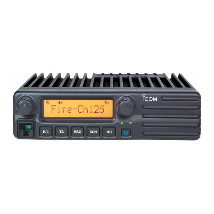
Page 6: I Function Display
PANEL DESCRIPTION I Function display y POWER SWITCH [POWER] Push to turn the power ON and OFF. • The following functions are available at power ON as options: - Automatic scan start - Password prompt - Set mode 1 3 6 . 1 N a r u TRANSMIT INDICATOR Lights red while transmitting. -
Page 7: I Programmable Function Keys
[DOWN], [P0], [P1], [P2], [P3] and [P4] programmable func- received, according to the pre-programming. tion keys. Consult your Icom dealer or system operator for details con- u CALL CODE MEMORY INDICATOR cerning your transceivers programming. Appears when the call code memory is selected. - Page 8 PANEL DESCRIPTION ZONE SELECT KEY SCAN TAG KEY Push this key, then select the desired zone using [CH Up]/ Push to add or delete the selected channel to/from the scan [CH Down]. group. What is “zone”?— The desired channels are assigned PRIORITY CHANNEL KEYS ➥...
- Page 9 PANEL DESCRIPTION PUBLIC ADDRESS KEY OUTPUT POWER SELECTION KEY While in the hailer mode, push this key for the audio output Push to select the transmit output power temporarily or per- via the hailer amplifier. Ask your dealer for details. manently, depending on the pre-setting.
- Page 10 PANEL DESCRIPTION DTMF RE-DIAL KEY TX CODE CHANNEL SELECT KEY ➥ Push to enter the ID code channel selection mode directly. Push to transmit the last-transmitted DTMF code. Then set the desired channel using [CH Up]/[CH Down]. CALL KEYS (p. 10) ➥...
- Page 11 PANEL DESCRIPTION USER SET MODE KEY D For Digital mode operation only ➥ Push and hold to enter user set mode. INDIVIDUAL KEY • During user set mode, push this key to select an item, and ➥ Push to enter the individual ID code selection mode directly. change the value or condition using push [CH Up]/[CH Down].
-
Page 12: Basic Operation
BASIC OPERATION I Turning power ON I Channel selection q Push [ ] to turn the power ON. Several types of channel selections are available. Methods w If the transceiver is programmed for a start up password, may differ according to your system set up. input the digit codes as directed by your dealer. -
Page 13: I Call Procedure
BASIC OPERATION I Call procedure I Receiving and transmitting When your system employs tone signaling (excluding CTCSS Receiving: q Push [ and DTCS), the call procedure may be necessary prior to voice ] to turn the power ON. transmission. The tone signalling employed may be a selec- w Push [CH Up] or [CH Down], or rotate [CH Up/Down] to tive calling system which allows you to call specific station(s) select a channel, in sequence. -
Page 14: D Transmitting Notes
BASIC OPERATION D Transmitting notes D TX code channel selection • Transmit inhibit function If the transceiver has [TX Code CH Select] assigned to it, the The transceiver has several inhibit functions which restrict indication can be toggled between the operating channel transmission under the following conditions: number (or name) and TX code channel number (or name). -
Page 15: D Tx Code Number Edit
BASIC OPERATION D TX code number edit USING [TX CODE ENTER] KEY: q Select the desired TX code channel via [TX Code CH (PMR or BIIS PMR operation only) Select]+[CH Up] or [CH Down], [TX Code CH Up], [TX If the transceiver has [TX Code CH Select] or [TX Code Code CH Down] or [TX Code CH Up/Down]. -
Page 16: D Individual Id Code Selection
BASIC OPERATION r Change the channel— cancels the selected Talkgroup ID D Individual ID code selection code (return to the pre-set Talkgroup ID code in the chan- (Digital mode operation only) nel.) If the transceiver has [Individual] assigned to it, the indication can be toggled between the operating channel number (or name) and Individual ID code (or name). -
Page 17: I User Set Mode
BASIC OPERATION I User set mode e Push [ User set mode is accessed with [User Set Mode] and allows ] again to exit set mode. you to set seldom-changed settings. In this case you can “customize” the transceiver operation to suit your preferences and operating style. -
Page 18: Biis Operation
BIIS OPERATION I Default setting I Receiving a call D D Individual call The following functions are assigned to each programmable q When an individual call is received; key as the default. However, the assigned function can be changed by your dealer. Ask your dealer for details. •... -
Page 19: D Group Call
BIIS OPERATION D D Group call D D Displaying the received call record q When a group call is received; — Queue indication • Beeps sound. The transceiver memorizes the calling station ID in the mem- • “ ” appears and the mute is released. ory. -
Page 20: I Transmitting A Call
BIIS OPERATION I Transmitting a call D D Calling back from the queue channel A total of 3 ways for code selection are available—selecting q While in the standby condition, push [P1] (Digital) for the call code from memory, entering the call code from the 1 sec. -
Page 21: D Direct Code Entry
BIIS OPERATION D D Direct code entry q While in the standby condition, push [P3] (TX Code Enter) u Push [PTT] to transmit; release to receive. i Push [P4] (Moni(Audi)) to send the ‘Clear down’ signal. to enter the TX code edit mode. •... -
Page 22: I Receiving A Message
BIIS OPERATION I Receiving a message D D Receiving a status message D D Receiving an SDM (Short Data Message) q When a status message is received; q When an SDM is received; • Beeps sound. • Beeps sound. • The calling station ID (or text) and the status message is dis- •... -
Page 23: D Received Message Selection
BIIS OPERATION D D Received message selection r Push [P1] (Digital) for 1 sec. again to return to the standby The transceiver memorizes the received message in the memory. Up to 6 messages for status and SDM, or 95 char- condition. -
Page 24: I Transmitting A Status
BIIS OPERATION I Transmitting a status D D General D D Transmitting a status q While in the standby condition, push [P1] (Digital), then The status message can be selected with the programmed text, and the message text is also displayed on the function push [Up] or [Down], or rotate [DIAL] to select the desired display of the called station. -
Page 25: I Transmitting An Sdm (Short Data Message)
BIIS OPERATION I Transmitting an SDM (Short Data Message) D D General D D Transmitting an SDM q While in the standby condition, push [P1] (Digital), then The short data message, SDM, can be sent to an individual station or group stations. Also, 8 SDM memory channels are push [Up] or [Down] or rotate [DIAL] to select the desired available and the messages can be edited via PC program- station/group code. -
Page 26: D Programming An Sdm Memory
BIIS OPERATION D D Programming an SDM memory • Available characters (IC-F1821/D or IC-F2821/D only) Characters q During standby condition, push [P1] (Digital) twice, then ! ? ' " , ; : _ ( ) < > [ ] push [Up] or [Down] to select the desired SDM to be edit- 1 (space) # * / + - = &... -
Page 27: I Position Data Transmission
BIIS OPERATION I Position data transmission I Digital ANI When the optional cable and a GPS receiver is connected to The own ID can be transmitted each time the PTT is pushed the transceiver, the position (longitude and latitude) data can (log-in) or released (log-off) during individual or group call be transmitted automatically. -
Page 28: I Stun Function
BIIS OPERATION I Stun function I Priority A channel selection When the specified ID, set as a killer ID, is received, the stun When one of the following operations is performed, the trans- function is activated. ceiver selects the Priority A channel automatically. When the killer ID is received, the transceiver switches to the Priority A is selected when;... -
Page 29: Connection And Maintenance
Connect a 4–8 Ω (IC-F1821/D or IC-F2821/D only. external speaker. IC-F1721/D and IC-F2721/D has a built-in speaker.) y DC POWER RECEPTACLE Connects to a 12 V DC battery. Pay atten- tion to polarities. NEVER connect to a 24 V battery. -
Page 30: I Supplied Accessories
CONNECTION AND MAINTENANCE I Supplied Accessories • Function name stickers Microphone Microphone hanger Microphone There are no names on the programmable function keys and screw set hanger cable since the functions can be freely assigned to these keys. Attach the supplied function name stickers as below to the appropriate keys for easy recognition of that key’s assigned function. -
Page 31: I Mounting The Transceiver
CONNECTION AND MAINTENANCE I Mounting the transceiver I Optional UT-111 installation The universal mounting bracket supplied with your transceiv- Install the optional UT-111 unit as follows: er allows overhead mounting. q Turn the power OFF, then disconnect the DC power cable. •... -
Page 32: I Optional Ut-109 Or Ut-110 Installation
CONNECTION AND MAINTENANCE I Optional UT-109 or UT-110 I Optional OPC-617 installation installation Install the OPC-617 as shown below. q Turn the power OFF, then disconnect the DC power cable. w Unscrew the 4 cover screws, then remove the bottom cover. e Cut the pattern on the PCB at the TX mic circuit (MIC) and RX AF circuit (AF OUT), then solder CP37 as shown below. -
Page 33: I Antenna
CONNECTION AND MAINTENANCE I Antenna I Options A key element in the performance of any communication sys- • RMK-2 SEPARATION KIT tem is an antenna. Contact your dealer about antennas and OPC-607/OPC-608/OPC-609 SEPARATION CABLE the best places to mount them. Allows you to install the transceiver main unit separately from the front panel for operating convenience. -
Page 34: Safety Training Information
1 meter separation distance. In order to ensure this During transmissions, your Icom radio generates RF energy that can distance is met, the installation of the antenna must be mounted possibly cause interference with other devices or systems. - Page 36 A-6406H-1EX Printed in Japan 1-1-32 Kamiminami, Hirano-ku, Osaka 547-0003, Japan © 2004 Icom Inc.
Need help?
Do you have a question about the IC-F1721 and is the answer not in the manual?
Questions and answers