Table of Contents
Advertisement
Advertisement
Table of Contents

Related Manuals for Q-See QSNDVR4R


Summary of Contents for Q-See QSNDVR4R
-
Page 1: Digital Video Recorder
Digital Video Recorder Rev 061807... - Page 2 4 Channel Digital Video Recorder Precautions & Safety Instructions Power Source This Digital-Video-Recorder uses a AC90-240 V power source. This recorder should only be operated using the specified power supply. Please check the voltage of the power supply before using. If you are not going to use the recorder for a long period of time, be sure to disconnect the power supply from the wall outlet.
- Page 3 4 Channel Digital Video Recorder Features Video input: 4 channels; video output: 2 Audio input: 4 channels; audio output: 1 Four optional levels of image quality: very high, high, normal and low. Record and playback frame rate changeable for recording. Compression standard: MJEPG NTSC / PAL compatible.
-
Page 4: Table Of Contents
4 Channel Digital Video Recorder Table of Contents TABLE OF CONTENTS SYSTEM CONNECTIONS................5 1. R ..................5 ANEL AND ONNECTION ERMINALS 2. V ......................6 IDEO AND UDIO ONNECTION 3. A ....................7 LARM AND ENSORS ONNECTION 4. H ........................9 ONNECTION SYSTEM SETUP....................10 1. - Page 5 4 Channel Digital Video Recorder DISPLAY STATUSES WHILE RUNNING..........32 1. S ....................32 CREEN ISPLAY HILE UNNING 2. S ....................33 CREEN ISPLAY HILE LAYING 3. TRIP D ........................... 33 ISPLAY USER GUIDELINE ..................35 1. T DVR........................35 URNING 2. T DVR ........................
-
Page 6: System Connections
4 Channel Digital Video Recorder APPENDIX D: INTERNET VIEW/PLAYBACK CONFIGURATION...60 1. Rear Panel and Connection Terminals Power cord, input and output signal terminals are all situated at the rear panel of the DVR. The connections to monitor(s), video cameras, and all external peripherals are through the terminals and sockets on the rear panel. -
Page 7: Video And Audio Connection
4 Channel Digital Video Recorder 7: NET INTERFACE 8: ALARM INPUT 9: ALARM OUTPUT 10: +5V 11: GROUND 12: RS485 PORT 2. Video and Audio Connection The DVR can support up to 4 cameras video input simultaneously. The monitor must be installed as shown in the diagram below. -
Page 8: Alarm And Sensors Connection
4 Channel Digital Video Recorder 3. Alarm and Sensors Connection (Requires professional installer) The DVR can support up to 4 alarms input and 3 alarms output. Alarm input: There are two types of alarm input. ( ) 1. Voltage output 5 V and 0V A: In case the sensor output is high voltage (5V) normally and output is low voltage when triggered (0V), then users must set the DVR for low voltage alarm. - Page 9 4 Channel Digital Video Recorder Alarm output There are three alarm output pins, the status of these pins are illustrated below: After alarm Before alarm Example for alarm output connection: Alarm...
-
Page 10: Hard Disk Connection
4 Channel Digital Video Recorder 4. Hard Disk Connection To install the Hard Disk follow the installation sequence illustrated below. Note: If the DVR comes with a HDD, skip the following steps. 1. Pull out the hard drive rack from the DVR Open the top cover of the drawer. -
Page 11: System Setup
4 Channel Digital Video Recorder Prior to use, program your desired settings, otherwise the DVR will run in the default settings. 1. Access to Menu To access the menu just press the Menu button in the front panel or the remote and the password input window will display as shown below. -
Page 12: Setup Options
4 Channel Digital Video Recorder 2. Setup Options When in SETUP MODE, press on either the UP or DOWN arrow buttons on the remote or front panel to scroll through the selection of settings. The selection will be highlighted in yellow. When choosing digital fields such as such as year, month, day, hour, minute, second, etc, press on the left or right arrow buttons on the remote or front panel. -
Page 13: Password Set
4 Channel Digital Video Recorder The following options are available: (1) TIME/DATE SET (See below) (2) HDD FORMAT SET (See below) (3) AUTOSEQUENCE SET (See below) (4) FACTORY RESET (See below) (5) PASSWORD SET (See below) (6) MENU LANGUAGE: Use “+” or “-” to modify this option. (7) PLAY REPEAT: If set to YES, when playing stored video in the HDD to the end, it will automatically replay video from the beginning, otherwise stops at the end. -
Page 14: Time/Date Set
4 Channel Digital Video Recorder ① PASSWORD CHANGE: Press the ENTER button to change the password. The user must enter the CURRENT PASSWORD first. If the current password is correct, the system will prompt to input the new password with CHANGE PASSWORD and then input again with CONFIRM PASSWORD. If the password is changed successfully, the screen will display PASSWORD CHANGED. -
Page 15: Hdd Format Set
4 Channel Digital Video Recorder appear as shown below. Note that if the DVR is in recording mode you cannot access this menu unless you stop recording first. Press UP, DOWN, LEFT, and RIGHT arrow buttons to move the cursor. Press “+” or “-” buttons in the front panel or the remote to set up the DATE and TIME values. -
Page 16: Auto Sequence Setup
4 Channel Digital Video Recorder If YES is selected and ENTER is pressed to confirm, all video files on the HDD will be lost in the reformatting process. Select NO to skip this operation. 7. Auto Sequence Setup Auto Sequence will display one camera at a time at specific intervals. Move the cursor to AUTOSEQ SET in the SYSTEM SETUP menu, press the ENTER button and the AUTO SETUP window will appear. -
Page 17: Factory Reset
4 Channel Digital Video Recorder to change the Auto Sequence time for each channel. 8. Factory Reset In the SYSTEM SETUP menu window, select FACTORY RESET then ENTER and a window to confirm will appear as illustrated below. If YES is selected and the ENTER button is pressed, the DVR will reset to default factory settings. To skip this operation, select and enter NO. -
Page 18: Camera Names Setup
4 Channel Digital Video Recorder 10. Camera Names Setup When the cursor moves to NAME SETUP in the VIDEO SETUP window, press the ENTER button and the cameras NAME SETUP window will appear. This is illustrated below. Pressing the UP or DOWN arrow buttons will select the channels separately. Press the ENTER button to change each channel’s name. -
Page 19: Brightness/Contrast Setup
4 Channel Digital Video Recorder DISPLAY: If set to OFF, the channel’s name will not display on the screen. 11. Brightness/Contrast Setup When the cursor moves to BRI/CON SETUP in the VIDEO SETUP window, press the ENTER button and the BRIGHT/CONTRAST SETUP window will appear. This is illustrated below. BRI: Picture Brightness CON: Picture Contrast Press the UP, DOWN, LEFT, and RIGHT arrow buttons in the front panel or remote to move the cursor... -
Page 20: Network Setup
4 Channel Digital Video Recorder OVER WRITE: If set to YES, the DVR will automatically overwrite the HDD when the HDD is full. If set to NO, the DVR will automatically stop recording when the HDD is full. REC SPEED: The DVR factory default setting for the recording frame rate is 30F/SEC (frames/second) under video standard NTSC (25F/SEC default under video standard PAL). -
Page 21: Mac Set
4 Channel Digital Video Recorder ENTER button results in the NETWORK SETUP menu window appearing. This is illustrated below. Note: If the PC View software from the Internet is connected to the DVR, this menu cannot be accessed unless the PC View software is closed. NETWORK STATE: Network Speed switch, if within a local network, select LOCAL_LAN;... -
Page 22: Alarm And Sensors Setup
4 Channel Digital Video Recorder If there is more than one DVR in a local area network, each DVR must be set to have an exclusive MAC Address. There is only one chance to modify the MAC Address. Once MAC ADDRESS is changed, this menu will not appear again. -
Page 23: Motion Detection Settings
4 Channel Digital Video Recorder The following Options are available in the SENSOR SETUP menu: (1) CHANNEL SELECT: Select the channel to set up. (2) ALARM ENABLE: Alarm trigger switch that can be set to OFF, LOW LEVEL or HIGH LEVEL; if set to OFF, the DVR will ignore the alarm input. - Page 24 4 Channel Digital Video Recorder For daytime hours, set the MOTION LEVEL detection sensitivity to NORMAL; at night set to LOW. 2) When surveying objects in 50-100 meters distance The objects 50-100 meters away will appear quite small on the screen. For daytime hours, set the motion detection sensitivity to HIGH level.
-
Page 25: Area Set
4 Channel Digital Video Recorder 17. Area Set When the cursor moves to AREA SET in the SENSOR SETUP menu, pressing the ENTER button will result in the image for AREA SETUP appearing. This is illustrated below. Pressing the up, down, left, right arrow buttons moves the cursor throughout the sub areas in the screen. -
Page 26: Schedule Set
4 Channel Digital Video Recorder There are two types of USBBACKUP SAVE: PICTURE and FILM. PICTURE mode will backup still pictures; MOVIE mode will backup real video. Press the “+” or “-” buttons in the front panel or remote to set the backup mode. Backup only works in playback mode. -
Page 27: Protocol Set
4 Channel Digital Video Recorder The weekly recording schedule is defined for a period of time each day, from Monday to Sunday. START: Start recording time STOP: Stop recording time Note: Manual record mode (activate recording at any time) and Schedule record mode (including motion detection record mode, sensor record mode and time schedule record mode) are not active simultaneously. - Page 28 4 Channel Digital Video Recorder CHANNEL SEL: Channel which is connected to the speed dome camera to control BAUD RATE: Changeable from 2400bps to 38400bps.The default value is 2400bps. DOME ADDR: Address of the speed dome, changeable from 0x00 to 0xff 。...
-
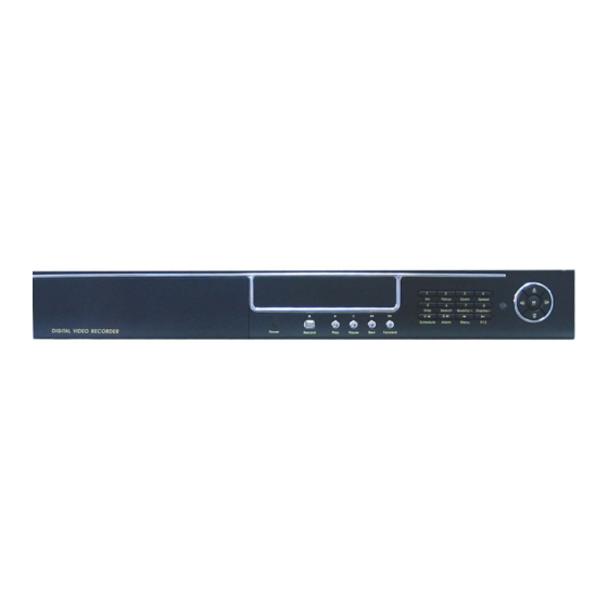
Page 29: Front Panel Buttons
4 Channel Digital Video Recorder The front panel of the video-recorder is illustrated below. 1.Recording/Playback Control Buttons 1. REC: This is the manual recording button. Press this button to record, re-press this button, it will stop recording. This function may require a password (if setup). This button is the toggle control for manual recording and stop recording operations. -
Page 30: Function Controls Area
4 Channel Digital Video Recorder 2. Function Controls Area 1. Auto/1: Auto key. Pressing this button puts the DVR in auto sequence mode. Sequences each channel image for the duration set in the Auto Sequence Set menu. Press any Channel Select button to quit this mode (see section below). -
Page 31: Channel Selection Controls Area
4 Channel Digital Video Recorder again to clear the information display. When inputting numbers this button is used to key in number “8”. When in System Setup menus, this is a “decrease” button. 9. PTZ/9: Press this button to access in sequence the PTZ Control operations for speed domes. See the section Pan-tilt-Zoom (PTZ) Operation in the User Guideline. - Page 32 4 Channel Digital Video Recorder press this button to move the cursor LEFT. 4. Fourth Channel/RIGHT: Press this button to see Channel 1 full screen. When selecting menu items, press this button to move the cursor RIGHT. all 4 channels video 5.
-
Page 33: Display Statuses While Running
4 Channel Digital Video Recorder 1. Screen Display While Running : Means DVR Schedule is on. : Means there is an Alarm input. : Channel 1 has an Alarm input. : Channel 1 Audio is on. : DVR is Recording Video now. -
Page 34: Screen Display While Playing
4 Channel Digital Video Recorder 2. Screen Display While Playing : DVR is playing video. : Live picture is off. PB: Playback 3. TRIP Display A sample screen is shown below: In TRIP Mode, there will be eight pictures on the screen: PB CH1 to PB CH4 is Playback Video, CAM... - Page 35 4 Channel Digital Video Recorder 1 to CAM4 are Live pictures, in this case OFF. Press the Trip button or any Channel Control button to exit TRIP Mode.
-
Page 36: User Guideline
4 Channel Digital Video Recorder 1. Turning ON the DVR The contents in the “Precautions and Safety Instructions” at the beginning of this manual must • be understood and always complied with. Read this section carefully. Before turning ON the DVR, check the system connections. All input and output peripherals and •... -
Page 37: Alarm Recording
4 Channel Digital Video Recorder (non-schedule status), pressing the REC button will record video of ALL active channels. Press the REC button to begin recording; four channels will start simultaneous recording. While • in normal recording mode, press the REC button again or the Stop button, enter the correct password (if RECORD PASSWORD is set to ON) and it will stop recording. -
Page 38: Time Recording
4 Channel Digital Video Recorder 5. Time Recording Time recording will begin and end automatically according to pre-determined time periods. • Recording is associated to a fixed timetable, for example, working hours or after hours recording with fixed start/stop times. It is setup via the SCHEDULE SETUP menu for a weekly schedule. See Schedule Set in the SYSTEM SETUP section of this manual. -
Page 39: Time Search
4 Channel Digital Video Recorder TIME SEARCH: Search play by input time. EVENT SEARCH: Search play by event list. START STOP SEARCH: Search play by segment. Press up and down arrow buttons to move the cursor, then press the ENTER button to enter the respective sub menu selected. -
Page 40: Event Search
4 Channel Digital Video Recorder Press the left and right arrow buttons to move the cursor to define a date and a time. Press the “+” and “-” buttons to modify the time fields. The START and END times will appear for the segment that contains the time entered. -
Page 41: Start Stop Search
4 Channel Digital Video Recorder If you have two HDD, and both have video data, press the Search button to change the HDD (toggle from Master to Slave). 10. Start Stop Search When the cursor moves to START STOP SEARCH in the SEARCH MODE menu, pressing the ENTER button will result in the RECORD SEARCH window appearing. -
Page 42: Zoom Operation
4 Channel Digital Video Recorder If you have two HDD, and both have video data, press the Search button to change the HDD (toggle from Master to Slave). 11. Zoom Operation Press the ZOOM button in the front panel (or simply press the ZOOM key on the remote) and the DVR will be in Zoom Mode. -
Page 43: Information Display
4 Channel Digital Video Recorder Pressing again the PIP button will change the PIP mode. Pressing and holding the PIP button can set each PIP picture. When one channel name is in yellow, push the left and right buttons to change the selected channel. -
Page 44: Usb Device Backup
4 Channel Digital Video Recorder HDD MODEL: HDD type HDD MAX: Capacity of hard disk(s) inserted in the DVR. HDD USED: Hard disk usage (%). OVERWRITE: Overwrite enabling, ON or OFF. REC SPEED: Frame rate speed for recording (fps). REC QUALITY: Recording quality. RESOLUTION: Recording resolution. -
Page 45: Pan -Tilt -Zoom (Ptz) Operation
4 Channel Digital Video Recorder Network Viewer software. To Playback the files, connect the USB Flash to a PC and run the Network Viewer program. • On the PC do a scan, click on Local Search and click on Open Folder and select the Flash Drive. Select the files and click on PLAY in Network Viewer. -
Page 46: Default Settings
4 Channel Digital Video Recorder 16. Default Settings “Defaults” are the initial setup by the manufacturer. The user can change the setup according to the actual environment and demands. If there is any confusion or unexpected effects or results, choose “Default Settings”... - Page 47 4 Channel Digital Video Recorder 60f/s~no use(NTSC) PB Speed NO use 50f/s~no use(PAL) Audio Enable CAM 1 CAM1~CAM4/OFF A/M REC Time 1 Minute 0~99minute Sub Net 255.255.255.0 Gate Way 192.168.1.1 Network IP Address 192.168.1.167 Settings Net Work State LOCAL_LAN LOCAL_LAN / EXTER_LAN N/W Enable ON/OFF Mac Address...
-
Page 48: Remote Control
4 Channel Digital Video Recorder 17. Remote Control All the functions of the DVR can be operated by the remote. 18. Serial Port Control To control the DVR through the RS485 port or to control the speed domes, make sure the protocol and baud rate are correct. - Page 49 4 Channel Digital Video Recorder CAT5 Cable. Open the software and the main control window below opens: Click the “Setting” button to open the window below. Enter the IP address and click “OK” button.
- Page 50 4 Channel Digital Video Recorder Enter the IP address. Check the default set or input values for AV Port, Command Port, Channel Enable, Video, etc. and click OK. Click the “Connect” button in the main window. The Logon window appears. Enter the password and click OK.
- Page 51 4 Channel Digital Video Recorder 2. STOP: Click to stop video play. 3. AVI: Click to save the video in AVI format on the computer. 4. LOCAL: Video is saved in the computer by clicking LOCAL. 5. Live Tab: Select this tab button to see video in real time. Click the PLAY button. 6.
- Page 52 4 Channel Digital Video Recorder Double click the Event to see the playback video. Note: The Select Record List operation is similar to the Event List operation. Scan Disk: Connect the HDD in the DVR to the PC as Slave and then select the Scan Disk tab. •...
- Page 53 4 Channel Digital Video Recorder : Camera swings up : Camera swings down : Camera swings left : Camera swings right : To fix the camera position : Lengthen focus : Shorten focus : Increase light amount for exposure : Decrease light amount for exposure (10) : ZOOM-IN (11)
-
Page 54: Standard And Product Specifications
4 Channel Digital Video Recorder I T E M I T E M S P E C I F I C A T I O N S P E C I F I C A T I O N I T E M I T E M S P E C I F I C A T I O N S P E C I F I C A T I O N... -
Page 55: Equipment And Accessories Supplied
4 Channel Digital Video Recorder 4 3 2 m m AUTO ZOOM TRIP 5 5 m m STOP SEARCH WM DISPLAY 7 0 m m MENU SCHEDULE P OWER PLAY PAUSE REW FORWARD 2 8 6 m m Name Quantity 4-channel hard disk video recorder Remote Power Cord... -
Page 56: Appendix A: Q&A Troubleshooting Guide
4 Channel Digital Video Recorder Q. What kind of cameras should I buy for this DVR? A. Any BNC or RCA interface indoor/outdoor/infrared camera will work with the DVR. It doesn’t matter whether it’s a color or black/white camera. However, web cameras that require a USB interface are not compatible with the DVR. - Page 57 4 Channel Digital Video Recorder PC operation system information and existing files on the hard disk drive. Q. What kind of hard disk drive should I purchase to make the DVR run? A. Any PC compatible IDE, ATA hard disk drive will work. Q.
- Page 58 4 Channel Digital Video Recorder Q. When the network connection between DVR and client computer is cut off, why does the DVR and the clock stop? A: In case the network is suddenly disconnected, the DVR will temporarily stop for 20 seconds without response to any pressing of the front panel buttons.
-
Page 59: Appendix B: Serial Port Protocol
4 Channel Digital Video Recorder Serial port setting: BAUD, n, 8, 1 (BAUD =2400, 4800, 9600, 19200,38400) PTC1: (three byte) Command (CHAR) Hexadecimal Number Function Description 0x2F 0x52 0x45 Record 0x2F 0x54 0x50 Play 0x2F 0x50 0x45 Pause 0x2F 0x52 0x54 Rewind 0x2F 0x46 0x54 Forward... - Page 60 4 Channel Digital Video Recorder Byte5~7 Refer to PTC 1 Same command as PTC 1 PTC3: (seven byte) Byte1 Byte2 Byte3 Byt4 Byte5 Byte6 Byte7 0xFF Addr Var1 Var2 Check sum Var1 Var2 Function PELCO-D 0x00 0x08 Ch1/up 0x00 0x10 Ch2/down Down 0x00...
-
Page 61: Appendix C: Recording Capacity For 120Gb Hdd
4 Channel Digital Video Recorder 0x06 Record 0x11 4/Trip 0x07 Play 0x12 5/Stop 0x08 Pause 0x13 6/Search 0x09 Reward 0x14 7/WM/Add 0x0A Forward 0x15 8/display/Dec 0x0B Menu 0x16 9/PTZ Note: This protocol is the same as PELCO-P’s call function; the PELCO-P’s call function can be used to control the DVR. -
Page 62: Network Configuration
4 Channel Digital Video Recorder office/home via HUB. 2): ADSL: User applies for ADSL from Internet services supplier and connect an ADSL MODEM. Connect the computer to the ADSL MODEM. Input user name and password in the dialing software so that users can connect to the Internet. - Page 63 4 Channel Digital Video Recorder 3): In case the connection to the Internet is by proxy server, users should utilize port mapping software and open ports 5000 –5002 for the surveillance computer. 4): In case users connect to the Internet by router, users should add the IP address of the surveillance computer and open the above mentioned ports in DMZ setup or via Virtual Server setup of the router (the names may be different for different types of routers).
- Page 64 4 Channel Digital Video Recorder...
- Page 65 4 Channel Digital Video Recorder Since ADSL and CABLE MODEM network users usually use dynamic IP addresses, once the MODEM restarts, the IP addresses will change. In this case, users should apply for DNS services. Version 2.0...
Need help?
Do you have a question about the QSNDVR4R and is the answer not in the manual?
Questions and answers