Fluke 9040 User Manual
Phase rotation indicator
Hide thumbs
Also See for 9040:
- User manual (14 pages) ,
- User manual (16 pages) ,
- Supplement manual (9 pages)
Table of Contents

Related Manuals for Fluke 9040


Summary of Contents for Fluke 9040
- Page 1 9040 Phase Rotation Indicator Users Manual PN 2438546 April 2005, Rev.2, 5/11 © 2005-2011 Fluke Corporation. All rights reserved. Specifications are subject to change without notice. All product names are trademarks of their respective companies.
- Page 2 LIMITED WARRANTY AND LIMITATION OF LIABILITY This Fluke product will be free from defects in material and workmanship for one year from the date of purchase. This warranty does not cover fuses, disposable batteries, or damage from accident, neglect, misuse, alteration, contamination, or abnormal conditions of operation or handling.
-
Page 3: Table Of Contents
Contacting Fluke ....................1 Unpacking the 9040 .................... 2 Safety Information ....................3 Symbols....................... 5 Elements of the 9040 ..................6 Determine the Rotary Field Direction ..............7 Maintaining the 9040 ................... 8 Replacing the Fuse (9040UK only) ..............9... -
Page 5: Introduction
9040 Introduction The Fluke 9040 Phase Rotation Indicator (the 9040) is a handheld instrument designed to detect the rotary field of three-phase systems. How to Contact Fluke To contact Fluke, call one of the following telephone numbers: • Technical Support USA: 1-800-44-FLUKE (1-800-443-5853) •... -
Page 6: Unpacking The 9040
9040 Users Manual Unpacking the 9040 The 9040 is available in three configurations. Depending on your purchase, the 9040 ships with these items: • 9040 o 3 self-retaining test probes, 1000 V CAT II o 3 alligator clips, 1000 V CAT III/600 V CAT IV o Users Manual •... -
Page 7: Safety Information
Phase Rotation Indicator Safety Information Safety Information Caution identifies conditions and actions that may damage the 9040. Warning identifies conditions and actions that pose hazard(s) to the user. XW Warning To prevent possible electrical shock, fire, or personal injury: •... - Page 8 Verify operation prior to measuring hazardous voltages (voltages above 30 V ac rms, 42 V ac peak and 60 V dc). • Do not use the 9040 with any of the parts removed. • Do not use the product around explosive gas, vapor, or in damp or wet...
-
Page 9: Symbols
Phase Rotation Indicator Symbols Symbols The following symbols appear on the 9040 or in this manual. Table 1. Symbols Risk of Danger. Important Earth ground. information. See manual. Hazardous voltage. Risk of Double Insulated. electric shock. Conforms to requirements of Conforms to relevant Canadian European Union. -
Page 10: Elements Of The 9040
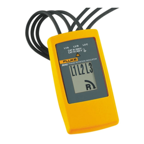
Elements of the 9040 Indicators, buttons, and jacks are shown in Figure 1. Test lead input jack L1, L2, L3 Indicators Clockwise Rotation LCD Indicator Counter-Clockwise Rotation LCD Indicator Brief Instructions on instrument rear bbx02f.eps Figure 1. The 9040 Phase Rotation Indicator... -
Page 11: Determine The Rotary Field Direction
XW Warning The rotary indicator lights even if the neutral conductor, N, is connected instead of L1, L2, or L3. Refer to the back of the 9040 for more information. Note The 9040 is powered from the installation under test. -
Page 12: Maintaining The 9040
Maintaining the 9040 W Caution To prevent damage to the 9040: • Do not attempt to repair or service the 9040 unless qualified to do so. • Make sure that the relevant calibration, performance test, and service information is being used. -
Page 13: Replacing The Fuse (9040Uk Only)
Phase Rotation Indicator Replacing the Fuse (9040UK only) Replacing the Fuse (9040UK only) XW Warning For safe operation and maintenance of the product: • Use only specified replacement fuses. See Specifications section. • Before you replace the fuse, disconnect the accessory (cable or probe) at both ends. -
Page 14: Specifications
9040 Users Manual Specifications Safety Specifications Electrical Safety Environmental IEC 61010-1/EN 61010 Operating Temperature 0 °C to +40 °C IEC 61557-7/EN 61557-7 Pollution Degree Maximum Operating Voltage (Ume) 690 V Type of Protection Protection Levels IP 40 CAT III/600 V to ground...
Need help?
Do you have a question about the 9040 and is the answer not in the manual?
Questions and answers