KitchenAid KXD4630YSS0 Use & Care Manual
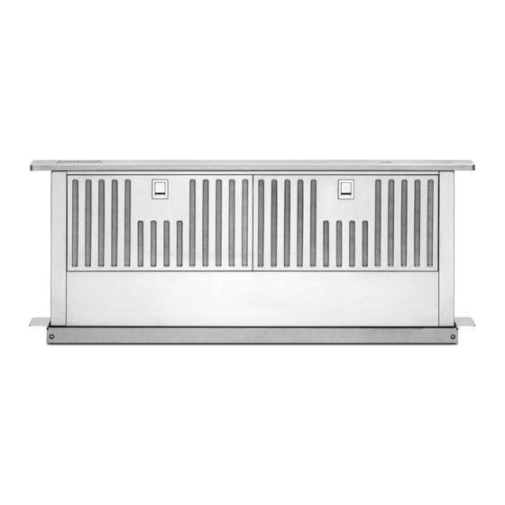
30" (76.2 cm) and 36" (91.4 cm) retractable (pop-up) downdraft vent system
Hide thumbs
Also See for KXD4630YSS0:
- Technical education (14 pages) ,
- Installation instructions and use & care manual (30 pages)
Table of Contents
Advertisement
Available languages
Available languages
I_itchen_kid
_
30" (76.2 CM) AND 36" (91.4 CM)
RETRACTABLE
(POP-UP) DOWNDRAFT
VENT
SYSTEM
For questions about features, operation/performance,
parts, accessories
or service, call: 1-800-422-1230
In Canada, for assistance,
installation and service, call: 1-800-807-6777
or visit our website at...
www.kitchenaid.com
or www.KitchenAid.ca
P
SYSTEME DE VENTILATION
RETRACTABLE
(CLAPET) DE 30" (76,2 CM) ET 36" (91,4 CM) -
ASPIRATION PAR LE BAS
Au Canada, pour assistance,
installation ou service composez le 1-800-807-6777
ou visitez notre site web &...
www.KitchenAid.ca
Table of Contents/Table
des matieres ............................................................................
2
IMPORTANT:
READ
AND
SAVE
THESE
iNSTRUCTIONS.
FOR
RESIDENTIAL
USE
ONLY.
IMPORTANT
: LIRE
ET CONSERVER
CES
INSTRUCTIONS.
POUR
UTILiSATION
RI_SIDENTIELLE
UNIQUEMENT.
LI3ZTB/W10342489D
Advertisement
Table of Contents

Related Manuals for KitchenAid KXD4630YSS0


Summary of Contents for KitchenAid KXD4630YSS0
- Page 1 1-800-422-1230 In Canada, for assistance, installation and service, call: 1-800-807-6777 or visit our website at... www.kitchenaid.com or www.KitchenAid.ca SYSTEME DE VENTILATION RETRACTABLE (CLAPET) DE 30" (76,2 CM) ET 36" (91,4 CM) - ASPIRATION PAR LE BAS Au Canada, pour assistance, installation ou service composez le 1-800-807-6777 ou visitez notre site web &...
- Page 2 TABLE OF CONTENTS VENT SYSTEM SAFETY ..............Install Downdraft Vent In-Line (External Type) Blower Motor..17 Make Electrical Connections for In-Line INSTALLATION REQUIREMENTS ..........Blower Motor System ..............Tools and Parts ................Make Electrical Power Supply Connection to Location Requirements ..............Downdraft Vent ................
-
Page 3: Vent System Safety
VENT SYSTEM SAFETY Your safety and the safety of others are very important. We have provided many important safety messages in this manual and on your appliance. Always read and obey all safety messages. This is the safety alert symbol. This symbol alerts you to potential hazards that can kill or hurt you and others. -
Page 4: Tools And Parts
INSTALLATION REQUIREMENTS _?' i_: _ _._1:_ Gather the required tools and parts before starting installation. NOTE: Downdraft vent is installed directly behind the cooktop. Read and follow the instructions provided with any tools listed Install the downdraft vent first, then install the cooktop. here. - Page 5 Product Dimensions Models with interior-mounted blower motor Models with exterior-mounted blower motor Top trim widths: 30" (76.2 cm) 36" (91.4 cm) 131/2'' (34.3 cm) retractable vent height (3.8 cm) 27" (68.6 cm) for 30" (76.2 cm) vent (0.95 cm) 33" (83.8 cm) for 36" (91.4 cm) vent Cabinet Dimensions Interior-mounted blower motor model...
- Page 6 Countertop Cutout Dimensions IMPORTANT: Countertops with a bull-nosed front edge are not recommended for these installations. Some models require a countertop deeper than 25" (63.5 cm); see the following Countertop Cutout Dimensions Chart. To avoid mistakes, it is recommended that the cooktop and vent cutouts be drawn on the countertop before making any cutouts. See Cooktop Installation Instructions for complete cutout dimensions, location dimensions and installation details.
-
Page 7: Venting Methods
Observe all governing codes and ordinances. If the house has aluminum wiring, follow the procedure below: Ensure that the electrical installation is adequate and in conformance with National Electrical Code, ANSI/NFPA 70 (latest 1. Connect a section of solid copper wire to the pigtail edition), or CSA Standards C22.1-94, Canadian Electrical Code, leads. - Page 8 INSTALLATION INSTRUCTIONS INTERIOR-MOUNTED VENT MOTOR Island Location--Vent System Installed Under a Concrete Determine which venting method is best for your application. Slab Using PVC Sewer Pipe Vent system can terminate either through the wall or floor. Island Location Front (Standard) Mounted Blower Motor Front (standard) mounted Rear mounted...
- Page 9 Calculating Vent System Length 31/4 '' x 10" (8.3 cm x 25.4 cm) 4.5 ft to 6" (15.2 cm) transition (1.4 m) 31¼ '' x 10" (8.3 x 25.4 cm) rectangular vent is required from the blower motor box. It can be transitioned to 6" (15.2 cm) round vent if needed.
-
Page 10: Rear Mounting - Blower Motor
Measure distance "X" from the cabinet floor to the top of the countertop. Subtract 28W' from distance "X" to determine dimension "Y" (X - 28V2 = Y). Excessive Weight Hazard Top of countertop Use two or more people to move and install downdraft vent. - Page 11 Left or Right Venting 1. Using two or more people, place the downdraft vent system on its back. NOTE: Optional blower motor rear mounting position (opposite 2. Remove the 4 screws from the cover plate mounted to the side) for island cabinet locations. The blower motor box face of the motor box and set them aside.
- Page 12 4. Lift the 1/4"(6.4 mm) deep cover off the shoulder screws in the keyhole slots and set the cover aside. 5. Remove the screws from the wire mounting plate. NOTE: The downdraft vent system is supplied with a 31/4 '' x 10" (8.3 x 25.4 cm) back draft damper and a 6"...
- Page 13 2. Remove 4 screws attaching the terminal box cover. Drill 2 pilot holes through each of the undercounter mounting brackets into the underside of the countertop. Using 2 screws (not provided) of the appropriate length, mount the brackets to the countertop. IMPORTANT: Select a screw length that will not allow the screws to go through the countertop when tightened.
- Page 14 5. Connect the 2 black wires together using UL listed wire connectors. 6. Replace the terminal box cover and secure with screw. 7. Reconnect power..I,_)I. Ol _.II]011 Push and hold the button on the top of the downdraft vent for a few seconds.
-
Page 15: Venting Methods
INSTALLATION INSTRUCTIONS EXTERIOR-MOUNTED VENT MOTOR CAUTION: To reduce the risk of fire and electrical shock, install NOTE: Exterior mounted vent motor installations require an the downdraft only with remote blower systems that are sold by approved in-line blower motor system. Model numbers Whirlpool Corporation. - Page 16 Measure distance "X" from the cabinet floor to the top of the countertop. Subtract 28V2" from distance "X" to determine dimension "Y" (X - 28V2" = Y). Excessive Weight Hazard Top of countertop Use two or more people to move and install downdraft vent.
- Page 17 Drill 2 pilot holes through each of the undercounter mounting brackets into the underside of the countertop. Using 2 screws (not provided) of the appropriate length, mount the brackets B!;o : _t::ed to the countertop. IMPORTANT: Select a screw length that will not allow the Remove 4 screws attaching the terminal box cover.
- Page 18 Prepare the In-line Blower System Install In-line Blower System NOTE: The blower motor housing can be mounted using 4 holes from either the inlet side or the outlet side of the blower. Outlet Side Excessive Weight Hazard Use two or more people to move and install in-line blower motor system.
- Page 19 Complete Preparation 1. Determine and make all necessary cuts for the vent system. IMPORTANT: When cutting or drilling into the floor, ceiling or wall, do not damage electrical wiring or other hidden utilities. 2. Determine the location where the 1/2"(1.3 cm) wiring conduit will be routed through the floor, ceiling or wall between the in- line blower and the downdraft vent.
- Page 20 Electrical Shock Hazard Electrically ground blower. Connect ground wire to green and yellow ground wire in terminal box. Electrical Shock Hazard Failure to do so can result in death or electrical shock. Disconnect power before servicing. Replace all parts and panels before operating. 8.
- Page 21 3. Use UL listed wire connectors and connect black wires (D) together. 4. Use UL listed wire connectors and connect white wires (B) Push and hold the button on the top of the downdraft vent for together. a few seconds. The retractable section of the downdraft vent will rise, and the blower will start.
- Page 22 VENT SYSTEM USE The retractable downdraft vent system is designed to remove For gas cooktops, the downdraft vent system may affect the smoke, cooking vapors and odors from the cooktop area. flame stability and cooking performance. To improve the burner performance, either decrease the downdraft vent •...
- Page 23 VENT SYSTEM CARE To avoid damaging the finish, clean downdraft vent with soap and water. Do not use scouring powder or abrasive solutions. Exterior Surfaces: Cleaning Method: To avoid damage to the exterior surface, do not use steel wool or •...
- Page 24 WIRING DIAGRAMS © Motor Specifications Power supply 120 VAC Frequency 60 Hz Wattage rating 420 W Amperage 3.7 A Motor Resistance BU/W 21.6 Ohms BU/R 18 Ohms BU/GY 14.3 Ohms BU/BK 9.8 Ohms _,_° --Oc° © Blower Switch Operation Contact Function 1st Speed 2nd Speed...
- Page 25 NOTE: Wiring for "0 "0 "0 "0 external blower motor E && & & o_ co [SEL0016521] ° >- >- £C ® >- c5 _ >- ( I.,,.,.,.,.,.,.,.,m, © __'-- ____/_ _.._¢ ._____ x___, f_._ :>R Motor Specifications Power supply 120 VAC Frequency 60 Hz...
- Page 26 For further assistance • Features and specifications on our full line of appliances. If you need further assistance, you can write to KitchenAid with • Installation information. any questions or concerns at: • Use and maintenance procedures.
- Page 27 YOU SPECIFIC LEGAL RIGHTS, AND YOU MAY ALSO HAVE OTHER RIGHTS WHICH VARY FROM STATE TO STATE OR PROVINCE TO PROVINCE. If outside the 50 United States and Canada, contact your authorized KitchenAid dealer to determine if another warranty applies. If you need service, first see the "Troubleshooting"...
-
Page 28: Securite Du Systeme De Ventilation
SECURITE DU SYSTEME DE VENTILATION Votre securite et celle des autres est tres importante. Nous donnons de nombreux messages de s_curit_ importants dans ce manuel et sur votre appareil m_nager. Assurez-vous toujours lire tousles messages de s_curit_ et de vous y conformer. Ce symbole d'alerte de s_curit_ vous signale les dangers potentiels de d_c_s et de blessures graves &... - Page 29 llVIPORTANTES iNSTRUCTiONS DE SI CURITI AVERTISSEMENT : POUR MINIMISER LE RISQUE AVERTISSEMENT : POUR REDUIRE LE RISQUE D'UN FEU DE GRAISSE SUR LA CUISINI_:RE : D'INCENDIE, CHOC ELECTRIQUE OU DOMMAGES CORPORELS, RESPECTER LES INSTRUCTIONS [] Ne jamais laisser un _16ment de surface fonctionner & SUIVANTES puissance de chauffage maximale sans surveillance.
-
Page 30: Exigences D'installation
EXIGENCES D'INSTALLATION {_ _s__ _ _i_!_,_ S Rassembler les outils et pieces necessaires avant d'entreprendre REMARQUE : Le systeme d'extraction par le bas est installe I'installation. Lire et observer les instructions fournies avec directement derriere la table de cuisson. Installer d'abord le chacun des outils de la liste ci-dessous. - Page 31 Dimensions duproduit Modeles a ventilateur montd a I'intdrieur Modeles a ventilateur montd a I'extdrieur Largeurs de la garniture sup_rieure: 30" (76,2 cm) 43/4"(1 ,1 cm) 36" (91,4 cm) 131/2`' (34,3 cm) hauteur de I'_vacuation r_tractable 131/8" (33,4 cm) (3,8 cm) E),95 cm) 27"...
- Page 32 Plan de travail - Dimensions des ouvertures _ d_couper IMPORTANT : Les plans de travail avec rebord avant arrondi ne sont pas recommandes pour ces installations. Certains modeles necessitent un plan de travail de plus de 25" (63,5 cm); voir le tableau des dimensions de I'ouverture du plan de travail.
- Page 33 Observer les dispositions de tousles codes et reglements en • Si le domicile possede un c&blage en aluminium, suivre la vigueur. procedure ci-dessous : S'assurer que I'installation electrique est correcte et qu'elle Raccorder une section de c&ble en cuivre massif aux satisfait aux exigences de la plus recente edition de la norme conducteurs en queue de cochon.
- Page 34 INSTRUCTIONS D'INSTALLATION VENTILATEUR MONTE A L'INTERIEUR Configuration en got-Circuit d'_vacuation install_ sous Determiner la methode d'evacuation la plus appropriee. La sortie une dalle de b_ton (utilisation de conduit de PVC I'exterieur du circuit d'evacuation peut se faire a travers le pour _gout) plancher ou a travers un mur.
- Page 35 Calcul de la Iongueur effective du circuit d'_vacuation Raccord de transition de 6" 1 pi (15,2 cm) vers 31A'' x 10" (0,3 m) Un conduit rectangulaire de 31¼"x 10" (8,3 x 25,4 cm) est (8,3 cm x 25,4 cm) necessaire pour la caisse du ventilateur. II peut _tre raccorde a un conduit rond de 6"...
- Page 36 c_ _'7_ ..Mesurer la distance "X" entre le sol et le dessus du plan de travail. Soustraire 281/2 '' de la distance "X" pour determiner la distance "Y" (X - 281/2= Y). Risque du poids e×cessif Dessus du plan de travail Utiliser deux ou plus de personnes pour d_placer et...
- Page 37 Sortie par le cet_ gauche ou le cet_ droit : 1. A deux personnes ou plus, poser I'arriere du systeme d'extraction par le bas face au sol. REMARQUE : Position de montage du ventilateur & I'arriere (c6te 2. Retirer les 4 vis du couvercle monte & I'avant de la caisse du oppose) possible pour les configurations en ilot.
- Page 38 4. Lever le couvercle d'epaisseur 1/4"(6,4 mm) pour le sortir des vis & epaulement dans les encoches en trou de serrure et le mettre de c6te. 5. Retirer les vis de la platine de montage du c&ble. REMARQUE : Le systeme d'extraction par le bas est livre avec un clapet anti-retour de 31/4'' x 10"...
- Page 39 2. Oter les 4 vis du couvercle du boitier de connexion. Percer 2 avant-trous & travers les equerres de fixation sous le plan de travail, dans la face inferieure du plan de travail. Avec 2 vis (non fournies) de la Iongueur adequate, fixer les equerres au plan de travail.
- Page 40 4. Raccorder les 2 conducteurs blancs avec les connecteurs ills (homologation UL). Risque de choc _lectrique D_connecter la source de courant _lectrique avant I'entretien. Replacer pi_ces et panneaux avant de faire la remise en marche. Le non=respect de ces instructions peut causer un d_c_s ou un choc _lectrique.
-
Page 41: Exigences D'emplacement
{_.,.. I ,, ,..I_. ,.I,,= [( l_.Id _I_I:01 _:I.]III[ Appuyer pendant quelques secondes sur le bouton au 2. Manceuvrer le curseur de commande sur le c6te de I'appareil sommet du systeme d'extraction par le bas. La partie pour verifier son fonctionnement et la vitesse du ventilateur. - Page 42 INSTRUCTIONS D'INSTALLATION VENTILATEUR MONTE A L'EXTERIEUR REMARQUE : L'installation d'un ventilateur monte & I'exterieur MISE EN GARDE : Afin de reduire le risque d'incendie ou de choc electrique, installer ce systeme d'extraction par le bas necessite un systeme de ventilation en ligne approuv& uniquement avec des ventilateurs installes &...
-
Page 43: Achever I'installation
Mesurer la distance "X" entre le sol et le dessus du plan de travail. Soustraire 281/2 '' de la distance "X" pour determiner la distance "Y" (X - 281/2 '' = Y). Risque du poids e×cessif Dessus du plan de travail Utiliser deux ou plus de personnes pour d_placer et... - Page 44 Oter les 4 vis du couvercle du boitier de connexion. 4. Percer 2 avant-trous & travers les equerres de fixation sous le plan de travail, dans la face inferieure du plan de travail. Avec 2 vis (non fournies) de la Iongueur adequate, fixer les equerres au plan de travail.
- Page 45 _ .._ _:s[;d lal o ._ _._ 4_-_ .._t_ _.<:_t ue_:t late_, ....• I }zj]e {tVl9 :_e×le_-:_le) dl _ " sy_:A :) ?}.e d ext_"ad • " ° <) ] ..1)_t t_¸ _=_ _ I,,.. _, REMARQUE : ke systime d'extraction...
- Page 46 Achever la preparation ..... 1. Determiner et effectuer toutes les decoupes necessaires pour le passage du circuit d'evacuation. IMPORTANT • Lors des operations de decoupe et de per(;age dans un plancher, un mur ou un plafond, veiller a ne pas endommager les c&blages electriques ou autres canalisations...
-
Page 47: Raccordements Electriques
Connecter les fils du c&ble du bas (5 ills) a I'interieur du boitier de connexion du systeme de ventilation retractable aux ills venant du conduit de c&blage du ventilateur en ligne & I'interieur du boitier de connexion du systeme de ventilation retractable. - Page 48 r _ _ _,o_ _,,-_ ,_ _ Risque de choc 61ectrique Relier le ventilateur/_ la terre. Brancher le fil reli_ a la terre au fil vertet jaune reli_ Risque de choc _lectrique la terre darts la boite de la borne. D_connecter la source de courant _lectrique avant...
- Page 49 Connecter le circuit d'evacuation au ventilateur. Le circuit REMARQUE : Pour tirer le plus grand ben6fice du systeme d'evacuation doit se terminer par une bouche de decharge (& d'extraction par le bas retractable, lire la section "Utilisation travers le mur ou le toit). Utiliser du ruban adhesif ou des systeme d'extraction".
- Page 50 ENTRETIEN DU SYSTEME D'EVACUATION I,,,_:_I I I,,_:_,.> i,I @X{{I;IEIOII Pour eviter d'endommager la finition, nettoyer les surfaces avec Toujours essuyer pour eviter de laisser des marques d'eau. de I'eau savonneuse. Ne pas utiliser une solution de recurage ou M_thode de nettoyage : un produit abrasif.
- Page 51 SCHEMAS DE CABLAGE © Caract6ristiques du moteur Alimentation 120 VCA JA!VE Fr6quence 60 Hz Puissance nominale 420 W Intensit6 3,7 A R6sistance du moteur BU/BL 21,6 ohms BU/R 18 ohms ® BU/GRIS 14,3 ohms BU/N 9,8 ohms ® °_O --Oc° Oc,o <...
- Page 52 REIVIARQUE : C&blage pour • • ¢ ventilateur & I'ext6rieur ® [SEL0016521 I ___ rr r'r <_ ,--O ® ,< 0"< co®. < "-0 CC _ GRIS GRIS Caract_ristiques du moteur Alimentation 120 VCA Fr_quence 60 Hz Puissance nominale 420 W Intensit_ 3,7 A R_sistance...
- Page 53 Telephoner au Centre pour I'eXperience de la clientele de Pour Iocaliser la compagnie de service designee par KitchenAid sans frais d'interurbain : 1-800-422-1230. KitchenAid dans votre region, vous pouvez aussi consulter les Pages jaunes de I'annuaire telephonique. Nos consultants sont prets a vous aider pour les questions suivantes •...
- Page 54 CONF#RE DES DROITS JURIDIQUES SP¢:CIFIQUES ET VOUS POUVEZ €:GALEMENT JOUIR D'AUTRES DROITS QUI PEUVENT VARIER D'UNE JURIDICTION A UNE AUTRE. Si vous residez a I'exterieur du Canada et des 50 €:tats des €:tats-Unis, contactez votre marchand KitchenAid autorise pour determiner si une autre garantie s'applique.
-
Page 56: In Canada
© 2011. All rights reserved. ® Registered Trademark/TM Trademark of KitchenAid, U.S.A., KitchenAid Canada licensee in Canada Printed in Mexico Tous droits reserves. ® Marque deposee/TM Marque de commerce de KitchenAid, U.S.A., Emploi sous licence par KitchenAid Canada au Canada Imprime au Mexique...
Need help?
Do you have a question about the KXD4630YSS0 and is the answer not in the manual?
Questions and answers