
Related Manuals for Nautilus NR 2000


Summary of Contents for Nautilus NR 2000
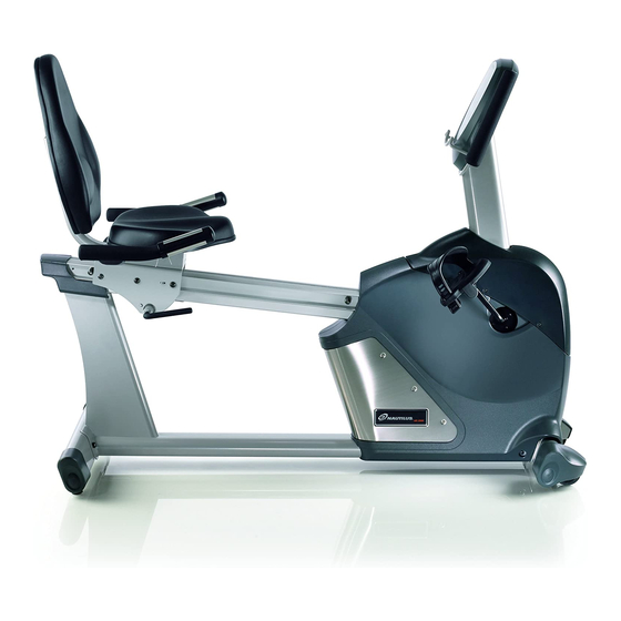
- Page 1 NR 2000 EXERCISE BIKE Assembly Manual PN 50008 Rev C (06/26/2007)
- Page 2 TOOLS AND HARDWARE...
-
Page 3: Table Of Contents
PARTS LIST ITEM NO. DESCRIPTION QTY. MAIN FRAME REAR STABILIZER M8x1.25x65 SOCKET HEAD CAP SCREW M8 SPRING WASHER M8 WASHER FRONT STABILIZER HANDLE BAR MAST HEART RATE SPRING WIRE UPPER SPEED SENSOR WIRE ADAPTOR SPEED SENSOR ASSEMBLY M8x1.25x15L SOCKET HEAD CAP SCREW BOOT SHROUD M5x0.8x12L FLAT HEAD SCREW M5x0.8x10L SCREW... -
Page 4: Assembly Instructions
ASSEMBLY INSTRUCTIONS STEP 1: Attaching the Rear Stabilizer Attach the rear stabilizer (2) to the base frame rear bracket, using 2 - 20mm socket head cap screws (22), 2 - spring washers (4) and 2 - washers (5). - Page 5 NR 2000 RECUMBENT BIKE STEP 2 : Attaching the Front Stabilizer Attach the front stabilizer (6) to the base frame front bracket, using 2 - 65mm socket head cap screws (3), 2 - spring washers (4) and 2 - washers (5).
-
Page 6: Main Frame
ASSEMBLY INSTRUCTIONS STEP 3: Installing Boot Shroud and Handlebar Mast Slide the boot shroud (13) up the handlebar mast (7). This part will be secured in place last. Plug the upper speed sensor wire (9) into the lower speed sensor wire (11). Plug the upper heart rate wire (32) into the lower heart rate wire (8). -
Page 7: Seat
NR 2000 RECUMBENT BIKE STEP 4: Installing Seat Frame Assembly Place seat handle assembly (17) on top of seat carriage frame (30). Feed the grip heart rate wire assembly (8) through hole is the seat handle assembly (17). Plug the grip heart rate wire assembly (8) into the grip heart rate connector (17A). Now attach the seat back support assembly (16) through the seat handle assembly (17) and into the seat carriage frame (30) using 4 - 55mm socket head cap screws (18), 4-spring washers (4) and 4 –washers (5). -
Page 8: Seat Back Cover
ASSEMBLY INSTRUCTIONS STEP 5: Installing the Seat Bottom and Seat Back Attach the seat bottom (19) to the seat handle assembly (17) with 4 - 20mm socket head cap screws (22), 4 – spring washers (4) and 4 - washer (5). Attach the seat back (20) to the seat back support assembly (16) with 4 –... -
Page 9: Handle Bar Assembly
NR 2000 RECUMBENT BIKE STEP 6: Installing Handlebar Assembly Attach the handlebar assembly (23) to the handlebar mast (7) with 2 – 40mm socket head cap screws (24), and 2 – washers (5). -
Page 10: Computer
ASSEMBLY INSTRUCTIONS STEP 7: Attaching the Computer Console Plug the upper speed sensor wire (9), and the upper heart rate wire (35) into the back of computer (25). Attach the computer (25) to the handlebar mast (7) using 4 – 10mm pan head screws (27). Then attach the computer lower case (26) to the computer (25) using 4 - 12mm pan head screws (28). - Page 11 NR 2000 RECUMBENT BIKE STEP 8: Installing the Water Bottle Holder Attach the water bottle holder (29) to the seat carriage (30) using 3 – 10mm pan head cap screws (15).
- Page 12 ASSEMBLY INSTRUCTIONS STEP 9: Installing Pedals and Pedal Straps Thread the right pedal (33R) marked with an "R" into the right side of the crank arm (52). Install the right pedal strap at desired length (34R) (Important: The thread direction of the right pedal is clockwise.) Thread the left pedal (33L) marked with an "L"...
- Page 13 NR 2000 RECUMBENT BIKE STEP 10: Installing Adapter Plug the 110 V adapter (10) into the plug outlet in the bike shroud. Now plug the adapter into the wall outlet. Note: There is not a power switch on the machine. Simply begin pedaling to activate computer.
- Page 14 ASSEMBLY INSTRUCTIONS Final Check Assembly of your Nautilus bike is now complete. Check again to insure that all parts are properly installed and that all nuts and bolts are completely secured. Get on the bike and check to see that the computer console and resistance system are working properly.
- Page 15 NR 2000 RECUMBENT BIKE...
- Page 16 The Nautilus Group 1886 Prairie Way Louisville, Colorado 80027 1.888.628.8458 www.nautilus.com © 2002 Nautilus, Inc. rev. C...
Need help?
Do you have a question about the NR 2000 and is the answer not in the manual?
Questions and answers