Table of Contents
Advertisement
™
Table of Contents
Section Code
Section
1
1
1
Reading the Product Specification Label
1
1
1
Leveling the Machine
1
Moving the Machine
1
1
1
1
1
1
2
Belt Tension Adjustment
3
4
Console
5
6
7
8
9
10
11
Data Cable in the Mast
12
13
14
15
16
17
Nautilus, Inc., www.NautilusInc.com, 5415 Centerpoint Parkway, Groveport, OH 43125 U.S.A. - Customer Service: North America (800) 605-3369, csnls@nautilus.com | outside U.S.
www.nautilusinternational.com | © 2016 Nautilus, Inc. | Nautilus, the Nautilus logo, and Nautilus Trainer are trademarks owned by or licensed to Nautilus, Inc. Inc., which are registered or
otherwise protected by common law in the United States and other countries. Polar
App Store is a service mark of Apple Inc. The Bluetooth
license.
8021148.101518.A
Nautilus
™
word mark and logos are registered trademarks owned by Bluetooth SIG, Inc., and any use of such marks by Nautilus, Inc. is under
®
ORIGINAL DOCUMENT - ENGLISH VERSION ONLY
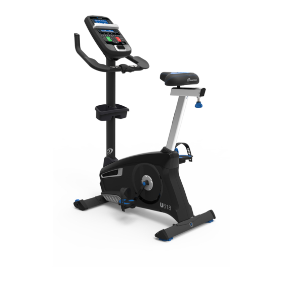
U618 Upright Bike Service Manual
™
Page Number
2
3
3
4
5
5
6
6
7
7
10
12
13
14
14
17
20
20
22
24
28
30
35
38
42
45
47
51
54
56
58
, OwnCode
, Google Play™, Under Armour
®
®
1
and MyFitnessPal
are trademarks of their respective owners.
®
®
Service Manual
8012455.101518.B
Advertisement
Table of Contents

Related Manuals for Nautilus U618


Summary of Contents for Nautilus U618
-
Page 1: Table Of Contents
Nautilus, Inc., www.NautilusInc.com, 5415 Centerpoint Parkway, Groveport, OH 43125 U.S.A. - Customer Service: North America (800) 605-3369, csnls@nautilus.com | outside U.S. www.nautilusinternational.com | © 2016 Nautilus, Inc. | Nautilus, the Nautilus logo, and Nautilus Trainer are trademarks owned by or licensed to Nautilus, Inc. Inc., which are registered or otherwise protected by common law in the United States and other countries. -
Page 2: Important Safety Instructions
Nautilus, Inc., www.NautilusInc.com, 5415 Centerpoint Parkway, Groveport, OH 43125 U.S.A. - Customer Service: North America (800) 605-3369, csnls@nautilus.com | outside U.S. www.nautilusinternational.com | © 2016 Nautilus, Inc. | Nautilus, the Nautilus logo, and Nautilus Trainer are trademarks owned by or licensed to Nautilus, Inc. Inc., which are registered or otherwise protected by common law in the United States and other countries. -
Page 3: Safety Warning Labels And Serial Number
Safety Warning Labels and Serial Number WARNING! • Injury or death is possible if caution is not used while using this machine. • Keep children and pets away. • Read and follow all warnings on this Serial number machine. • Refer to the Owner’s Manual for additional warnings and safety Product specification... -
Page 4: Specifications
Specifications 147.4 kg (325 lbs.) Maximum User Weight: Total Surface Area (footprint) of equipment: 5670 cm2 Machine Weight: 37.7 kg (83.1 lbs.) Power Requirements: Input Voltage: 100 - 240V AC, 50/60Hz Output Voltage: 9VDC, 1.5A Heart Rate Chest Strap: 1 CR2032 battery 148cm (58.3”) DO NOT dispose of this product as refuse. This product is to be recycled. -
Page 5: Maintenance
Maintenance Read all maintenance instructions fully before you start any repair work. In some conditions, an assistant is neces- sary to do the necessary tasks. Equipment must be regularly examined for damage and repairs. The owner is responsible to make sure that regular maintenance is done. -
Page 6: Connectivity
Bluetooth Connectivity with the “Nautilus Trainer™” Fitness App ® This fitness machine is equipped with Bluetooth connectivity and can wirelessly sync with the “Nautilus Trainer™” ® Fitness App on supported devices. The Software App syncs with your fitness machine to track total calories burned, time, distance, and more. It records and stores every workout for quick reference. Plus, it automatically syncs your workout data... -
Page 7: Heart Rate Chest Strap Battery Replacement
Heart Rate Chest Strap Battery Replacement The heart rate (HR) chest strap uses a CR2032 battery. Do not perform this procedure outdoors or in moist or wet locations. Using a coin, loosen the slotted cover on the battery bay. Remove the cover and battery. - Page 8 Condition/Problem Things to Check Solution Check User Profile Select the Edit User Profile option for the User Profile. Go to the WIRELESS HR setting and make sure that the current value is set to ON. Interference Try moving unit away from sources of interference (TV, Micro- wave, etc). Replace Chest Strap If interference is eliminated and HR does not function, replace strap. Replace Console If HR still does not function, replace Console.
- Page 9 Consult your device to be sure that the Bluetooth wireless ® ® feature has been enabled on it. Fitness App Review Specifications of Fitness App and confirm your device is compatible. Contact appsupport@nautilus.com (if inside US/Canada) or your local distributor (if outside US/Canada) for further assistance. Workout results not post- Sync accounts From the Menu icon on the Nautilus Trainer™ App, select the ing from Nautilus Trainer Sync to MyFitnessPal or Under Armour Connected Fitness.
-
Page 10: Console Service Mode
Console Service Mode – x618 series Consoles The Console Setup Mode lets you input the date and time, set the units of measurement to either English or Metric, change the machine type, control the sound settings ( on/ off), or see maintenance statistics (Total Run Hours – for service technician use only). - Page 11 g. RUN LED TEST – Drives LEDs to the following states: All LEDs On 1 second All LEDs Off 1 second Sequence Segments 1 at a time – on 1 second, off 1 second Press any key to exit test h. RUN LCD TEST – Drives 3x5 and 1x5 LCD displays with the following patterns: All segments on All segments off Set individual segments one at a time until all segments are illuminated. Press any key to exit.
-
Page 12: Maintenance Parts Exploded View
Maintenance Parts Exploded View Your machine may differ. Use only as a guide. U618 Console CHR Sensors RPM Sensor Console Mast Seat Speed Sensor Magnet Pedals Seat Post w/ Slider Servo Motor Crank Arms Adjustment Knob Drive Belt Left Shroud AC Adapter Drive Pulley... -
Page 13: Replacement Procedure Skill Level
REPLACEMENT PROCEDURE SKILL LEVEL Level I : Low - very little mechanical knowledge or exposure. Level II : Intermediate - some experience with mechanical procedures Level III : Advanced - knowledgeable about mechanical procedures Disconnect all power to the machine before you service it. When disposing of old parts, obey the applicable local and provincial requirements. For instructions to replace the following parts, please refer to the Assembly Manual for your bike: • AC Adapter • Seat • Seat Post •... - Page 14 Nautilus, Inc., www.NautilusInc.com, 5415 Centerpoint Parkway, Groveport, OH 43125 U.S.A. - Customer Service: North America (800) 605-3369, csnls@nautilus.com | outside U.S. www.nautilusinternational.com | © 2016 Nautilus, Inc. | Nautilus and the Nautilus logo are trademarks owned by or licensed to Nautilus, Inc. Inc., which are registered or otherwise protected by common law in the United States and other countries.
- Page 15 NOTICE: It is necessary to remove the Shrouds for this procedure. Refer to the “Replace the Shrouds” procedure. Disconnect all power to the machine before you service it. Note: Your machine may not match the image. For reference only. Figure 1 1.
- Page 16 6. Reassembly is the reverse procedure. NOTICE: Be sure not to crimp any cables. Final Inspection Inspect your machine to ensure that all hardware is tight and components are properly assembled. Do not use until the machine has been fully assembled and inspected for correct performance in accordance with the Owner’s Manual.
-
Page 17: Set The Brake Tension (Calibration)
Nautilus, Inc., www.NautilusInc.com, 5415 Centerpoint Parkway, Groveport, OH 43125 U.S.A. - Customer Service: North America (800) 605-3369, csnls@nautilus.com | outside U.S. www.nautilusinternational.com | © 2016 Nautilus, Inc. | Nautilus and the Nautilus logo are trademarks owned by or licensed to Nautilus, Inc. Inc., which are registered or otherwise protected by common law in the United States and other countries. - Page 18 NOTICE: It is necessary to remove the shrouds for this procedure. Refer to the “Replace the Shrouds” procedure. Note: Your machine may not match the image. For reference only. 1. Disconnect and reconnect the AC Adapter from the wall outlet to turn the power off and on. 2. Push QuickStart and verify that the console shows that the default resistance level is 4.
- Page 19 7. To adjust the Brake tension, loosen the 2 hex head bolts (C) and move the Servo Motor assembly (D) until the closest point on the Brake Magnet (A) is within 3.0 mm (1/8”) of the Flywheel (B). Tighten the bolts. Note: If the cardboard is not 3mm (1/8”) thick, you can use the pages of a paperback book to measure the gap. Approximately 36 pages (sheets) = 3mm. 8.
-
Page 20: Part Replacement
Nautilus, Inc., www.NautilusInc.com, 5415 Centerpoint Parkway, Groveport, OH 43125 U.S.A. - Customer Service: North America (800) 605-3369, csnls@nautilus.com | outside U.S. www.nautilusinternational.com | © 2016 Nautilus, Inc. | Nautilus and the Nautilus logo are trademarks owned by or licensed to Nautilus, Inc. Inc., which are registered or otherwise protected by common law in the United States and other countries. - Page 21 Disconnect all power to the machine before you service it. Note: Your machine may not match the image. For reference only. 1. Press the edges of the Console Pivot Shroud to disen- gage the tabs from the Console. Remove the Console Pivot Shroud and set it safely aside.
- Page 22 Nautilus, Inc., www.NautilusInc.com, 5415 Centerpoint Parkway, Groveport, OH 43125 U.S.A. - Customer Service: North America (800) 605-3369, csnls@nautilus.com | outside U.S. www.nautilusinternational.com | © 2016 Nautilus, Inc. | Nautilus and the Nautilus logo are trademarks owned by or licensed to Nautilus, Inc. Inc., which are registered or otherwise protected by common law in the United States and other countries.
-
Page 23: Pedals
Note: Your machine may not match the image. For reference only. 1. Loosen and remove the old Pedals. Discard the old Pedals. Note: T he Left Pedal is reverse-threaded. Orientation is based from a seated position on the bike. The Left Pedal has an “L”, the Right Pedal an “R”. 2. - Page 24 Nautilus, Inc., www.NautilusInc.com, 5415 Centerpoint Parkway, Groveport, OH 43125 U.S.A. - Customer Service: North America (800) 605-3369, csnls@nautilus.com | outside U.S. www.nautilusinternational.com | © 2016 Nautilus, Inc. | Nautilus and the Nautilus logo are trademarks owned by or licensed to Nautilus, Inc. Inc., which are registered or otherwise protected by common law in the United States and other countries.
- Page 25 Note: Your machine may not match the image. For reference only. 1. Loosen and remove the old Pedals. Set them safely aside for reassembly. Note: The Left Pedal is reverse-threaded. Orientation is based from a seated position on the bike. The Left Pedal has an “L”, the Right Pedal an “R”.
-
Page 26: Crank Arms
4. Thread the Crank Puller into the Crank Arm (B). When the Crank Puller is in the correct position, only 1-2 threads on the outer portion (CP2) of the Crank Puller should show. Note: Be sure the end of the Bolt (CP1) of the Crank Puller is flush with the Nut (CP2) as shown, before use. Using a wrench, turn the inner portion (CP3) of the Crank Puller clockwise. The Crank Arm (B) will slide off as it is tightened. Crank arm shown is on a 170 bike. - Page 27 Installation is the reverse procedure. Installation does not require the use of the crank puller. Be sure the Crank Arms are connected at 180° from each other. To reinstall the Pedals, carefully align the threads and hand tighten to prevent cross-threading. Then tighten fully with pedal wrench. Note: The Left Pedal is reverse-threaded. Be sure to attach Pedals on the correct side of the Bike.
-
Page 28: Transport Wheels, Front Endcaps And Footpads
Nautilus, Inc., www.NautilusInc.com, 5415 Centerpoint Parkway, Groveport, OH 43125 U.S.A. - Customer Service: North America (800) 605-3369, csnls@nautilus.com | outside U.S. www.nautilusinternational.com | © 2016 Nautilus, Inc. | Nautilus and the Nautilus logo are trademarks owned by or licensed to Nautilus, Inc. Inc., which are registered or otherwise protected by common law in the United States and other countries. - Page 29 Note: Your machine may not match the image. For reference only. 1. Place a static object (like a book or box) under the front stabilizer (C). The static object should not be compressible. 2. Using a short #2 Phillips screwdriver, loosen and remove the screws (A1) from the Footpad (A), and set them safely aside. Remove the Footpad from the front stabilizer (D). Set the Footpad and screws safely aside. 3. Loosen and remove the screw (B1) from the Endcap assembly (B) and set it safely aside.
- Page 30 Nautilus, Inc., www.NautilusInc.com, 5415 Centerpoint Parkway, Groveport, OH 43125 U.S.A. - Customer Service: North America (800) 605-3369, csnls@nautilus.com | outside U.S. www.nautilusinternational.com | © 2016 Nautilus, Inc. | Nautilus and the Nautilus logo are trademarks owned by or licensed to Nautilus, Inc. Inc., which are registered or otherwise protected by common law in the United States and other countries.
- Page 31 Disconnect all power to the machine before you service it. Note: Your machine may not match the image. For reference only. 1. Remove the Seat Post and the Seat Adjustment Knob (A). Set them safely aside for reassembly. 2. Using a flathead screwdriver, remove the threaded Cap (B) from the Crank Arm (C) to expose the Hex Head Bolt (D). 3. Using a wrench and socket, remove the Hex Head Bolt (D) . 4. Thread the Crank Puller into the Crank Arm (C). When the Crank Puller is in the correct position, only 1-2 threads on the outer portion (CP2) of the Crank Puller should show. Note: Be sure the end of the Bolt (CP1) of the Crank Puller is flush with the Nut (CP2) as shown, before use.
-
Page 32: Shrouds
7. Slide the Mast Gasket up the Mast. 8. Remove the hardware (indicated) from the Mast. Gently pull the Mast out and disconnect the cables. Set the hard- ware, Mast and Mast Gasket safely aside. NOTICE: Do not crimp the cables. This step may require two people. - Page 33 10. Using a #2 Phillips Screwdriver, remove the 6 screws (indicated) that secure the Left Shroud. Remove the bottom screws first, and then the top screws. Slowly remove the Left Shroud. Note: Find the Power Inlet (E) in the Left Shroud. Disconnect the Power Inlet cable (E1) from the wiring harness (F). NOTICE: Be sure not to crimp any cables.
- Page 34 11. Using a #2 Phillips Screwdriver, remove the 3 screws that secure the Right Shroud. Remove the bottom screws first, and then the top screw. Slowly remove the Right Shroud. 12. Installation is the reverse procedure. Put the Left Shroud in postion first to align the screws for the Right Shroud. Install the top screws first. NOTICE: Be sure not to crimp any cables. Be sure the tabs in the Top Shroud snap into the Main Assembly.
-
Page 35: Handlebar Assembly
Nautilus, Inc., www.NautilusInc.com, 5415 Centerpoint Parkway, Groveport, OH 43125 U.S.A. - Customer Service: North America (800) 605-3369, csnls@nautilus.com | outside U.S. www.nautilusinternational.com | © 2016 Nautilus, Inc. | Nautilus and the Nautilus logo are trademarks owned by or licensed to Nautilus, Inc. Inc., which are registered or otherwise protected by common law in the United States and other countries. - Page 36 Disconnect all power to the machine before you service it. Note: Your machine may not match the image. For reference only. 1. Press the edges of the Console Pivot Shroud to disen- gage the tabs from the Console. Remove the Console Pivot Shroud and set it safely aside.
- Page 37 6. Remove the T-handle and washers that attach the Handlebar to the Mast. Set them safely aside for reassembly. NOTICE: Hold the Handlebar so that it does not fall. Untie the string from the HR Cable and Resistance Cable. Remove the old Handlebar and discard it. 8. Put the replacement Handlebar in the bracket, adjust the Handlebar to the desired angle, and install the T-handle through the holes.
- Page 38 Nautilus, Inc., www.NautilusInc.com, 5415 Centerpoint Parkway, Groveport, OH 43125 U.S.A. - Customer Service: North America (800) 605-3369, csnls@nautilus.com | outside U.S. www.nautilusinternational.com | © 2016 Nautilus, Inc. | Nautilus and the Nautilus logo are trademarks owned by or licensed to Nautilus, Inc. Inc., which are registered or otherwise protected by common law in the United States and other countries.
- Page 39 Disconnect all power to the machine before you service it. Note: Your machine may not match the image. For reference only. 1. Press the edges of the Console Pivot Shroud to disen- gage the tabs from the Console. Remove the Console Pivot Shroud and set it safely aside.
- Page 40 6. Remove the T-handle and washers that attach the Handlebar to the Mast. Set them safely aside for reassembly. NOTICE: Hold the Handlebar so that it does not fall. Remove the Handlebar and set it safely aside for reassembly. 8. Remove the Mast Gasket. 9. Remove the hardware (indicated) from the Mast. Gently pull the Mast out and disconnect the cables. Set the hard- ware, Mast Gasket and Top Shroud safely aside for reas- sembly.
- Page 41 11. Put the Handlebar in the bracket, adjust the Handlebar to the desired angle, and install the T-handle through the holes and washers. NOTICE: Do not crimp the cables. 12. Use the pull cable in the Handlebar Bracket to route the HR cable and Resistance cable through the slot under the Handlebar Bracket to the top of the mast.
-
Page 42: Console Mast
Nautilus, Inc., www.NautilusInc.com, 5415 Centerpoint Parkway, Groveport, OH 43125 U.S.A. - Customer Service: North America (800) 605-3369, csnls@nautilus.com | outside U.S. www.nautilusinternational.com | © 2016 Nautilus, Inc. | Nautilus and the Nautilus logo are trademarks owned by or licensed to Nautilus, Inc. Inc., which are registered or otherwise protected by common law in the United States and other countries. - Page 43 Disconnect all power to the machine before you service it. Note: Your machine may not match the image. For reference only. 1. Press the edges of the Console Pivot Shroud to disen- gage the tabs from the Console. Remove the Console Pivot Shroud and set it safely aside.
- Page 44 6. Tie the length of string to the end (A) of the Data Cable at the base of the Mast. Hold the other end of the Data Cable (B) and carefully pull it out of the Mast so that the string extends through the length of the Mast. Untie the string from the old Data Cable and discard the old cable. NOTICE: Do not crimp the HR cable (C) and Resistance Cable (D).
-
Page 45: Brake Assembly
Nautilus, Inc., www.NautilusInc.com, 5415 Centerpoint Parkway, Groveport, OH 43125 U.S.A. - Customer Service: North America (800) 605-3369, csnls@nautilus.com | outside U.S. www.nautilusinternational.com | © 2016 Nautilus, Inc. | Nautilus and the Nautilus logo are trademarks owned by or licensed to Nautilus, Inc. Inc., which are registered or otherwise protected by common law in the United States and other countries. - Page 46 NOTICE: It is necessary to remove the Shrouds for this procedure. Refer to the “Replace the Shrouds” procedure. It may be necessary to adjust the Brake tension at the end of this procedure. Refer to the “Set the Brake Tension” procedure. Disconnect all power to the machine before you service it.
- Page 47 Nautilus, Inc., www.NautilusInc.com, 5415 Centerpoint Parkway, Groveport, OH 43125 U.S.A. - Customer Service: North America (800) 605-3369, csnls@nautilus.com | outside U.S. www.nautilusinternational.com | © 2016 Nautilus, Inc. | Nautilus and the Nautilus logo are trademarks owned by or licensed to Nautilus, Inc. Inc., which are registered or otherwise protected by common law in the United States and other countries.
- Page 48 NOTICE: It is necessary to remove the Shrouds for this procedure. Refer to the “Replace the Shrouds” procedure. It may be necessary to adjust the Brake tension at the end of this procedure. Refer to the “Set the Brake Tension” procedure. Disconnect all power to the machine before you service it.
-
Page 49: Servo Motor
Observe the cable routing. Disconnect the Speed Sensor Cable (D) and Power Inlet Cable (E) from the wiring harness (F). Tie the length of string to the end of the lower Console Cable (G) at the top of the Mast mount. Pull the cable and string down through the hole (H) at the base of the Mast so that the string extends through the mast. - Page 50 13. Reinstall the Mast, Console, Mast Gasket and Top Shroud. (Refer to the “Replace the Shrouds” procedure.) Turn the power on. Machine is on. Current is active. There is risk of electrical shock. 14. Use the console to set the resistance to the highest level.
-
Page 51: Drive Belt And Flywheel Assembly
Nautilus, Inc., www.NautilusInc.com, 5415 Centerpoint Parkway, Groveport, OH 43125 U.S.A. - Customer Service: North America (800) 605-3369, csnls@nautilus.com | outside U.S. www.nautilusinternational.com | © 2016 Nautilus, Inc. | Nautilus and the Nautilus logo are trademarks owned by or licensed to Nautilus, Inc. Inc., which are registered or otherwise protected by common law in the United States and other countries. - Page 52 NOTICE: It is necessary to remove the Shrouds for this procedure. Refer to the “Replace the Shrouds” procedure. It is necessary to adjust the Drive Belt tension at the end of this procedure. Refer to the “Belt Tension Adjustment” procedure. Disconnect all power to the machine before you service it.
- Page 53 Using needlenose pliers, carefully release the spring (E1) on the Belt Tensioner (E). To remove the hardware from the Flywheel (C), use the 15 mm open end wrench to hold the nut (F) on one side steady and remove the nut on the opposite side with the 15 mm socket and wrench.
-
Page 54: Belt Tensioner Assembly (Idler Assembly)
Nautilus, Inc., www.NautilusInc.com, 5415 Centerpoint Parkway, Groveport, OH 43125 U.S.A. - Customer Service: North America (800) 605-3369, csnls@nautilus.com | outside U.S. www.nautilusinternational.com | © 2016 Nautilus, Inc. | Nautilus and the Nautilus logo are trademarks owned by or licensed to Nautilus, Inc. Inc., which are registered or otherwise protected by common law in the United States and other countries. - Page 55 NOTICE: It is necessary to remove the Shrouds for this procedure. Refer to the “Replace the Shrouds” procedure. It is necessary to adjust the Drive Belt tension at the end of this procedure. Refer to the “Belt Tension Adjustment” procedure Disconnect all power to the machine before you service it.
-
Page 56: Rpm Sensor (Speed Sensor)
Nautilus, Inc., www.NautilusInc.com, 5415 Centerpoint Parkway, Groveport, OH 43125 U.S.A. - Customer Service: North America (800) 605-3369, csnls@nautilus.com | outside U.S. www.nautilusinternational.com | © 2016 Nautilus, Inc. | Nautilus and the Nautilus logo are trademarks owned by or licensed to Nautilus, Inc. Inc., which are registered or otherwise protected by common law in the United States and other countries. - Page 57 NOTICE: It is necessary to remove the Shrouds for this procedure. Refer to the “Replace the Shrouds” procedure. Disconnect all power to the machine before you service it. Note: Your machine may not match the image. For reference only. Carefully remove the Shrouds. Refer to the “Replace the Shrouds”...
-
Page 58: Power Inlet
Nautilus, Inc., www.NautilusInc.com, 5415 Centerpoint Parkway, Groveport, OH 43125 U.S.A. - Customer Service: North America (800) 605-3369, csnls@nautilus.com | outside U.S. www.nautilusinternational.com | © 2016 Nautilus, Inc. | Nautilus and the Nautilus logo are trademarks owned by or licensed to Nautilus, Inc. Inc., which are registered or otherwise protected by common law in the United States and other countries. - Page 59 NOTICE: It is necessary to remove the Shrouds for this procedure. Refer to the “Replace the Shrouds” procedure. Disconnect all power to the machine before you service it. Note: Your machine may not match the image. For reference only. Carefully remove the Left Shroud. Refer to the “Replace the Shrouds”...
- Page 60 3. Loosen and remove the thin Nut from the Power Inlet (C) on the outside of the Shroud. 4. Pull the Power Inlet plug (C) out of the hole toward the inside of the Shroud. Discard the old Power Inlet assembly. Installation is the reverse procedure.
Need help?
Do you have a question about the U618 and is the answer not in the manual?
Questions and answers