Nautilus R916 Service Manual
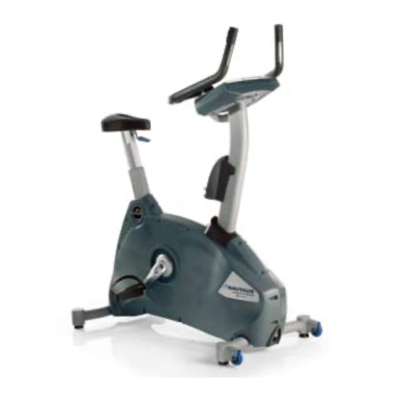
Commercial series bike
Hide thumbs
Also See for R916:
- Owner's manual (52 pages) ,
- Assembly manual (19 pages) ,
- Assembly manual (38 pages)

Related Manuals for Nautilus R916


Summary of Contents for Nautilus R916
- Page 1 Be Strong. ™ Model U916 Model R916 Service Manual Commercial Series Bike Model: U916 & R916 PN 001-6884 Rev B (03/27/2007)
- Page 2 Important—Please Read This manual is intended for authorized Nautilus or Nautilus certified service personnel and not for the consumer. There are no user serviceable parts. Servicing of the Nautilus ® Commercial Series Bike by other than authorized Nautilus or Nautilus certified service personnel may result in voiding of the warranty.
-
Page 3: Table Of Contents
..........13 Overview..............15 Defaults..............15 Customize...............15 Machine.Status............16 Diagnostics.............17 Maintenance.Logs..........18 Machine.Configuration...........20 Electrical Troubleshooting .......21 U916/R916.Main.Wiring.Diagram......23 U916.Console.Heart.Rate.Wiring.Diagram....24 R916.Console.Heart.Rate.Wiring.Diagram....25 General.Bike.Electronics.Troubleshooting.....26 Mechanical Troubleshooting ....35 Removing/Replacing.Parts.-. U916.and.R916.Common.Parts......37 Removing/Replacing.Parts.-. U916.Parts..............48 Removing/Replacing.Parts.-. R916.Parts..............51 Nautilus® Commerical Series Bike Service Manual... - Page 4 Contents...
-
Page 5: Product Specifications
C-Safe Compatible Level 2 compatible. Owner/manager will be able to customize console. Operating Temperature 50–90 F (10–32 Storage Temperature -25–50 Operating Humidity (non- 3–95% relative humidity condensing) Storage Humidty (non- 3–95% relative humidity condensing) Nautilus® Commerical Series Bike Service Manual... -
Page 6: Important Safety Information
Failure to follow the conditions set forth below shall limit, to the extent or dropped in water. Contact our Technical Service Department to allowed by law, Nautilus, Inc. responsibility for the safety, reliability, arrange for the return of damaged parts. -
Page 7: Safety.warning.labels
Warning LabeLs The.following.safety.warnings.are.located.on.the.Nautilus ® .Commercial.Series.Bike..Please.read.all.safety.precautions.and. warning.information.prior.to.using.your.product..Be.sure.to.replace.any.warning.label.if.damaged,.illegible,.or.missing...If. you.need.replacement.labels,.please.call.a.Nautilus.Representative.at.(800).628-8458.(North.America).or.+41-26-460-77-77. (International.office). Label 2 Label 1 Label 2 Label 1 Nautilus® Commerical Series Bike Service Manual... -
Page 8: Safety Warning Labels
safety Warning LabeLs The.following.safety.warnings.are.located.on.the.unit..Please.review.and.understand.the.safety.warning.labels.and.their. locations.on.the.unit.prior.to.use.. If.you.do.not.have,.or.cannot.find,.or.need.to.replace.a.warning.label.please.call.1-800-628-8458.(North.America).or.. +41-26-460-77-77.(International.office).to.obtain.a.new.label.. Label 1: See.Figure.1.for.general.warning.label.. Location:.. T he.warning.label.in.Figure.1.is.located.on.the. side.of.the.console.mast. figure 1 Label 2: See Figure 2 for general exercise warning label. figure 2 Location: Affixed.to.the.console.face.below.the.keypanel. -
Page 9: Maintenance
Maintenance Contents Maintenance.Records.................. 11 Resetting.the.Maintenance.Hour.Timer............11 Routine.Maintenance.................. 11 Checking.the.Battery.Charge............... 11 Recharging.the.Battery.Back-up..............12 Battery.Disposal................... 12 Nautilus® Commerical Series Bike Service Manual... -
Page 11: Maintenance.records
1. Frame: Inspect the frame for any rust, bubbling, or paint chips during the weekly cleaning. The salt in perspiration can damage the unpainted surfaces. Repair the damaged area with a touch-up paint kit purchased from Nautilus (call Customer Service for order information). -
Page 12: Recharging.the.battery.back-Up
Maintenance Recharging the Battery Back-Up The Commercial Series U916 and R916 bikes are both self-powered (cordless) with a rechargeable battery back-up. Typically, the bike can be operated without plugging in the battery charger. If, however, the console flickers during operation or the console display does not light up while using the machine, then use the battery charger to recharge the battery back-up. -
Page 13: Console Codes
Console Codes Contents Overview...................... 15 Defaults......................15 Customize..................... 15 Machine.Status.................... 16 Diagnostics....................17 Maintenance.Logs..................18 Reset.Maintenance.Hours............... 19 Error.Log....................19 Machine.Configuration................20 Nautilus® Commerical Series Bike Service Manual... -
Page 15: Overview
CHR PERCENT, AGE, TIME, LEVEL, WEIGHT EnTER Selected choice ▼ or ▲ (or numeric keypad) Default value changes EnTER DEFAULTS CLEAR SELECT WORKOUT Customize You.can.customize.several.console.settings.on.the.R916/U916.Bike.with.default.values.to.conform.to.your.individual. requirements,.including: •. resetting.all.configurable.settings.to.factory.defaults.(see.below) •.. adjusting.lower.screen.contrast.(0-15). •.. adjusting.upper.screen.contrast.(0-15). •.. console.language. •.. choosing.type.of.heartrate.inputs.(description.below) Nautilus® Commerical Series Bike Service Manual... -
Page 16: Machine.status
Machine Status •.. change.units.(USA.units.or.metric.units) •.. cooldown.time.(1-10.min) •.. maximum.time.limit.(10-99.min.or.OFF) Refer.to.the.following.table.to.scan.through.and.customize.the.settings:. Table 2–2. Customize Step No. Press Keys Display (What you will see) ▲, 3, ENTER CUSTOMIZE ▼ or ▲ SET DEFAULTS, CONTRAST ADJ LOWER, CONTRAST ADJ UPPER, LANGUAGE, SELECT STATS*, HR INPUTS, CHANGE UNITS, COOL DOWN, MAX TIME LIMIT ENTER Selected choice... -
Page 17: Diagnostics
100.in.the.Maintenance.Logs.service.screen.and.there.was.1.hour.of.running.time.on.the.machine,.the.value.under.this. Maint.Hours.screen.would.read.101). Machine Type.–.should.display.U/R916..“NTM.Config.REQD”.appears.on.the.console.if.the.software.has.been.updated.on. the.machine.or.the.machine.froze.up.and.the.power.had.to.be.cycled..The.message.also.appears.when.the.console.assembly. has.been.replaced.and.no.configuration.established..Configuring.the.machine.will.eliminate.this.message.(see.the.table. “Machine.Configuration”). Distance.–.displays.the.total.distance.in.miles.(or.kilometers).of.machine.operation...This.value.is.auto-incremented.every. 1/100th.or.1/10th.unit,.depending.on.how.many.miles/km.have.accrued. Workouts.–.displays.the.total.number.of.workouts.performed.on.the.machine...This.value.is.auto-incremented.only.if.the. user.enters.a.workout.and.either.completes.the.workout.or.presses.the.[STOP].key.twice. Run Hours.–.displays.the.total.number.of.hours.on.the.machine. noTE:.. T he.R&D.options.(codes.starting.with.5).are.not.used.for.servicing.machines..Do.not.change.these.settings..If.an. R&D.setting.is.inadvertently.changed,.it.will.reset.when.the.machine.is.powered.off.and.then.back.on. Diagnostics Use.diagnostic.codes.to.test.various.components.of.the.machine.such.as.the: •. tachometer. •. alternator •. I/O •. sensor.(for.EV9.16.only) •. serial.ports •. keypad. •. display Nautilus® Commerical Series Bike Service Manual... -
Page 18: Maintenance.logs
Maintenance Logs Refer.to.the.following.table.to.scan.through.the.diagnostic.tests.and.view.diagnostic.information: Table 2–4. Diagnostics Step No. Press Keys Display (What you will see) ▲, 6, ENTER DIAGNOSTICS ▼ or ▲ TACH TEST, ALT TEST, I/O TEST, A SENSOR B, SERIAL PORTS, KEY TEST, DISPLAY TEST ENTER Selected choice clEaR DIAGNOSTICS clEaR... - Page 19 MAINTENANCE LOGS ▼, ▼, ▼ ERROR LOG ENTER NO ERROR or the highest priority error ▼ or ▲ Scrolls through the error log list clEaR SELECT WORKOUT Error Log.–.displays.fatal.errors.accrued.on.the.system..The.log.holds.up.to.8.error.entries..Errors.are.handled.in.two.ways: First,.as.a.non-fatal.Warning,.which.will.display.the.error.response.text.but.continue.system.operation.until.you. press.the.[CLEAR].key..Warnings.are.not.logged.in.the.Error.Log. The.second.way.is.a.fatal.Error,.which.will.stop.the.exercise.and.return.the.system.to.an.idle.intensity.state..The. console.will.display.the.error.response.and.a.number.showing.how.many.errors.were.logged.during.the.specific. event..(Some.errors.trigger.multiple.responses)..To.view.the.non-displayed.errors,.access.the.Error.Log..The.unit.will. not.let.you.restart.the.program.unless.power.has.been.turned.off.and.then.back.on. Nautilus® Commerical Series Bike Service Manual...
-
Page 20: Machine.configuration
Machine Status Once.you.access.the.Error.Log,.you.can.cycle.the.display.through.8.entries.by.using.the.up/down.keys..Each.entry.displays. the.error.label,.its.position.in.the.log.(1-8),.and.the.time.(hours).the.error.occurred..Note.that.the.most.recent.error.might. not.be.in.log.position.1—as.the.number.of.errors.exceeds.8,.the.newest.error.will.overwrite.the.oldest..In.addition,.if.a.new. error.is.identical.to.the.log’s.previous.entry,.the.system.checks.the.time..If.the.time.is.the.same.(within.minutes),.the.error.is. not.logged,.to.help.prevent.redundant.errors. The.only.way.to.reset.the.Error.Log.is.to.reconfigure.the.machine. Machine Configuration Use.Machine.Configuration.to.change.the.machine.type..The.choices.are: •..Stepper. •..StepMill. •..U/R916 •..Elliptical In.general,.only.the.U/R916.machine.type.is.used.for.the.U916.or.R916. Refer.to.the.following.table.to.scan.through.and.customize.the.settings: Table 2–8. Machine Configuration Step No. Press Keys Display (What you will see) ▲, 8, EnTER CHANGE MACHINE EnTER U/R916 ▼ or ▲ NTM CONFIG RQD, STEPPER CL, STEPMILL, U/R916 ELLIPTICAL,... -
Page 21: Electrical Troubleshooting
Electrical Troubleshooting Contents U916.and.R916.Main.Power.Wiring.Diagram......... 23 U916.Console.Heart.Rate.Wiring.Diagram..........24 R916.Console.Heart.Rate.Wiring.Diagram..........25 General.Bike.Electronics.Troubleshooting..........26 Contact.Heart.Rate.Testing..............28 Battery.Charge.Testing................29 Alternator.Testing..................30 Start-Up.Circuit.Testing................31 Load.Resistor.Testing................32 Shut-Down.Testing.................. 33 Nautilus® Commerical Series Bike Service Manual... - Page 22 Electrical Troubleshooting...
-
Page 23: U916/R916.Main.wiring.diagram
U916/R916 Main Power Wiring Diagram Nautilus® Commerical Series Bike Service Manual... -
Page 24: U916.Console.heart.rate.wiring.diagram
U916 Console Heart Rate Wiring Diagram... -
Page 25: R916.Console.heart.rate.wiring.diagram
R916 Console Heart Rate Wiring Diagram Nautilus® Commerical Series Bike Service Manual... -
Page 26: General.bike.electronics.troubleshooting
General Bike Electronics Troubleshooting Perform general bike electrical testing With external power removed, pedal the bike at 25RPM or greater Using external Does power supply, the console battery in a charge battery for turn on? charged state? 8 hours Remove plastic Hold both Contact shrouds so Heart Rate grips... - Page 27 Approximately 1 minute after pedaling stops, the console should Replace main shut off Replace console interface cable the console shut off? General bike electrical testing Perform Shut- Down Testing Bike Is Operating Properly! Nautilus® Commerical Series Bike Service Manual...
-
Page 28: Contact.heart.rate.testing
Contact Heart Rate Testing Contact Heart Rate Testing Remove the screws securing Turn on console, the Contact Heart by either pedaling Rate plates bike, or installing external power supply Remove 4 screws Using volt meter, holding console to measure voltage mast potential on ALL Contact Heart... -
Page 29: Battery.charge.testing
Batteries can only be tested under load. Even if it measures 6V or more unloaded, it can still produce little or no voltage under load as a defective battery's internal impedance increases. Nautilus® Commerical Series Bike Service Manual... -
Page 30: Alternator.testing
Alternator Testing To minimize the complexity of the flowchart, this section will best be described in terms of system theory. The colored connections to the alternator are as follows: White-B+ — Alternator output voltage Brown-Field — Alternator Control Current Black-Ground — Alternator return Prior to proceeding with tests below, perform continuity checks on the alternator cable, and confirm cable is securely fastened to the alternator and the 27451 PCB. -
Page 31: Start-Up.circuit.testing
General bike contact from the electrical testing sensor Voltage Continuity measure 4VAC or more? Replace or repair Replace 27451 Replace the Replace console main interface magnetic pick-up cable General bike electrical testing Nautilus® Commerical Series Bike Service Manual... -
Page 32: Load.resistor.testing
Load Resistor Testing Load Resistor Testing Remove plastic shrouds so electronics can be observed Measure resistance from the 27451's J6 pin 3 to the alternator's B+ terminal Is the Is the Is the resistance .33 resistance high? resistance low? +/- 3%? Have a helper Resolve any loose Resolve any... -
Page 33: Shut-Down.testing
Measure the keep the console voltage potential of powered if J5 pin 9 and 10 externally powered General bike this close to 0V? electrical testing Replace the 27451 Replace the console General bike electrical testing Nautilus® Commerical Series Bike Service Manual... - Page 34 Electrical Troubleshooting...
-
Page 35: Mechanical Troubleshooting
Removing.the.Right.and.Left.Pedals..........39 Removing.the.Load.Resistor............40 Removing.the.Battery..............41 Removing.the.Power.Board............41 Removing.the.Power.Inlet.Connector..........42 Removing.the.Speed.Sensor............43 Removing.the.Alternator..............44 Removing.the.HTD.Belt..............46 Removing.the.Poly-V.Wheel............47 Removing/Replacing.Parts.-.U916.Parts............48 Removing.the.Upper.Handle.Bar............ 48 Replacing.the.Upper.Right.or.Left.CHR.Plates....... 48 Nautilus® Commerical Series Bike Service Manual... - Page 36 Mechanical Troubleshooting Replacing.the.Lower.T-Bar.Right.or.Left.CHR.Plates...... 49 Removing.the.Seat.Assembly............50 Removing.the.Side.Covers.............. 50 Removing/Replacing.Parts.-.R916.Parts............51 Removing.the.Side.Covers.............. 51 Removing.the.Left.and.Right.Rear.Covers........52 Cable.Connections.-.U916................53 Cable.Connections.-.R916................56...
-
Page 37: Removing/Replacing.parts.-. U916.And.r916.Common.parts
Mast so that you can connect the cables to the Console (R916 console shown) PC board (Figure 2). For specific connector locations, refer to the CABLE CONNECTIONS segment later in this section. Nautilus® Commerical Series Bike Service Manual... - Page 38 Mechanical Procedures Step 5: Install the Console to the Mast using the four Phil- lips screws that you removed in Step 1. See Figure 1a and 1b. REMOVING THE MAST: Tools needed: Phillips screwdriver or Cordless drill with Phillips tip 6 mm Allen wrench figure 3a - Remove right mast cover 8 mm Allen wrench...
- Page 39 Step 4: Using a 15mm Wrench, turn the pedal nut counter- clockwise to loosen and remove the pedal (Figure figure 8 - Loosen right pedal nut Nautilus® Commerical Series Bike Service Manual...
- Page 40 Mechanical Procedures REMOVING THE LOAD RESISTOR: Tools needed: Phillips screwdriver or Cordless drill with Phillips tip 5/16 Nut driver Step 1: Remove the right and left side covers according to the appropriate REMOVING THE SIDE COVERS procedure (U916 or R916). figure 9a - Detach resistor wires (U916) Step 2: Using a 5/16 Nutdriver and Phillips screwdriver, remove the hardware attaching the black and white...
- Page 41 REMOVING THE SIDE COVERS procedure (U916 and R916).” Step 2: Disconnect the attaching cables from Power board. figure 14a - Disconnect power board cables See Figure 14a and 14b. (U916 shown) Nautilus® Commerical Series Bike Service Manual...
- Page 42 Mechanical Procedures figure 14b - Power board cables disconnected (R916 shown) Step 3: Remove the four mounting screws at the corners of the Power board. See Figure 15 (U916 shown). figure 15 - Power board mounting screws REMOVING THE POWER INLET CONNECTOR: Tools needed: #0 Phillips screwdriver Wire cutters...
- Page 43 Step 1: Remove the right and left side covers according to the appropriate REMOVING THE SIDE COVERS proce- dure (U916 or R916). Step 2: Cut the cable tie from the wire bundle. See Figure 20. figure 20 - Cut cable tie Nautilus® Commerical Series Bike Service Manual...
- Page 44 Mechanical Procedures Step 3: Disconnect the cable end of the Speed Sensor from J2 on the Power board and remove the wire from the bundle. See Figure 21. figure 21 - Disconnect speed sensor cable Step 4: Loosen the adjustment screw and remove the Speed Sensor from the Alternator (Figure 22).
- Page 45 Step 6: Using a 6mm Allen wrench, 8mm Allen wrench, and 9/16 socket with ratchet, remove the two bolts that attach the Alternator to the frame. See Figure 27a and 27b. figure 27a - Remove alternator mounting bolts figure 27b - Nautilus® Commerical Series Bike Service Manual...
- Page 46 Mechanical Procedures Step 7: Remove the Speed Sensor from the old Alternator ac- cording to the REMOVING THE SPEED SENSOR proce- dure, and install the Speed Sensor on the new Alterna- tor. See Figure 28. Note: When placing the sensor on the Alternator, be sure the spacing between fan blade and the Sen- figure 28 - sor is .020 - .040...
- Page 47 Step 3: Using a 3/16 Allen wrench, loosen and remove the four mounting screws. See Figure 32. figure 32 - Step 4: Remove the Snap ring (Figure 33) and pull off the Poly- V wheel. Snap ring figure 33 - Nautilus® Commerical Series Bike Service Manual...
-
Page 48: Removing/Replacing.parts.-. U916.Parts
Mechanical Procedures U916 Procedures REMOVING THE UPPER HANDLEBAR: Tools needed: Phillips screwdriver or Cordless drill with Phillips tip 6 mm Allen wrench Step 1: Remove the console according to REMOVING THE CONSOLE procedure. figure 34 - Step 2: Remove the four Allen screws attaching the Handlebar to the frame with a 6mm Allen wrench. -
Page 49: Replacing.the.lower.t-Bar.right.or.left.chr.plates
Step 3: Disconnect the red CHR wire from the top plate and place to the side. figure 40 - Step 4: Reverse the steps when reinstalling the plates. Note: Be careful not to pinch the cable wires when reattaching the Front and Rear housings. Nautilus® Commerical Series Bike Service Manual... -
Page 50: Removing.the.seat.assembly
Mechanical Procedures REMOVING THE SEAT ASSEMBLy: Step 1: Press and hold the adjustment seat lever, then pull seat upward, straight out of the frame. See Figure 41a and 41b. figure 41a - figure 41b - REMOVING THE SIDE COVERS: Tools needed: Phillips screwdriver or Cordless drill with Phillips tip Step 1: Position yourself on the left side of the bike, and remove the 13 phillips screws from the left side cover. -
Page 51: Removing/Replacing.parts.-. R916.Parts
46 - Step 4: Position yourself on the right side of the bike, and remove the one phillips screw located near the Mast from the right side cover. See Figure 47. figure 47 - Nautilus® Commerical Series Bike Service Manual... -
Page 52: Removing.the.left.and.right.rear.covers
Mechanical Procedures Step 5: Position the right pedal so the cover may be carefully lifted and removed. See Figure 48. figure 48 - REMOVING THE LEFT AND RIGHT REAR COVERS: Tools needed: Phillips screwdriver or Cordless drill with Phillips tip Step 1: Remove the left and right Front covers according to the REMOVING THE LEFT AND RIGHT FRONT COVERS procedure. -
Page 53: Cable.connections.-.U916
Cable Connections - U916 Cable Connections - U916 Routing.and.connector.points.for.the.main.U916.cable.connections.are.shown.below...Wiring.diagrams.for.the.U916. console,.handles.and.main.power.are.provided.in.Section.2. Main and Tv Cables - Frame to Front Mast: Cables.exit.from.Mast Connect.the.attached.long.Wire.Tie.to.the MAST main.and.TV.cables.and.use.it.to.pull.the cables.up.through.the.Mast...Discard.the Wire.Tie.after.use. noTE:..TAKE.CARE.NOT.TO.PINCH.CABLES. WHEN.ASSEMBLING. Cables.enter.Mast WIRE.TIE CABLES MAIN.FRAME Nautilus® Commerical Series Bike Service Manual... - Page 54 Cable Connections - U916 HR Cables - Handlebars to Front Mast: Connect.the.attached.long.Wire.Tie.to.the handlebar.cables.and.use.it.to.pull.the cables.out.through.the.Mast...Discard.the Wire.Tie.after.use...(The.main.and.TV.cables. are.not.shown,.for.clarity.) noTE:..TAKE.CARE.NOT.TO.PINCH.CABLES. HANDLEBARS WHEN.ASSEMBLING. WIRE.TIE CABLES Cables.enter.Mast. through.handlebar. Cables.exit. support.arm from.Mast .MAST...
- Page 55 Figure B - Ferrite Bead Housing Reconnected connector.labeled.P1.on.the.back.of.the.console. Plug.the.Left.Heart.Rate.Wire.into.the.P2 connector. Plug.the.Center.Heart.Rate.Wire.into.the.P3 connector. Gently.push.the.excess.wires.back.down.into. Ferrite.Bead.Housing the.mast. TV.Cables noTE:..If.installing.the.optional.LCD.Monitor. refer.to.the.NV915.installation.manual.at.this. time..If.not.installing.the.LCD.Monitor,.wrap.the. end.of.the.TV.Cables.with.electrical.tape.and. tuck.them.into.the.Mast. CONSOLE Back of Console: P3 J5 Right.Heart.Rate.Wire Left.Heart.Rate.Wire Center.Heart.Rate.Wire Main.Console.Wire Ferrite.Bead.Housing TV.Cables .MAST Nautilus® Commerical Series Bike Service Manual...
-
Page 56: Cable.connections.-.R916
Cable Connections - R916 Cable Connections - R916 Routing.and.connector.points.for.the.main.R916.cable.connections.are.shown.below...Wiring.diagrams.for.the.R916. console,.handles.and.main.power.are.provided.in.Section.2. Main and Tv Cables - Frame to Front Mast: Connect.the.attached.long.Wire.Tie.to.the main.and.TV.cables.and.use.it.to.pull.the cables.up.through.the.Mast...Discard.the Cables.exit.from.Mast Wire.Tie.after.use. noTE:..TAKE.CARE.NOT.TO.PINCH.CABLES. WHEN.ASSEMBLING. MAST Mast attached to Main Frame: Cables.exit. from.Mast WIRE.TIE Cables.enter.Mast CABLES MAIN.FRAME... - Page 57 Main and HR Cables - Front Mast to Console: Plug.the.Main.Console.Wire.into.the.large CONSOLE connector.labeled.J5.on.the.back.of.the. Console. The.Right.Heart.Rate.Wire.is.labeled.with. an.“R”...Plug.the.Right.Heart.Rate.Wire.into. the.connector.labeled.P1.on.the.back.of.the. console. MAIN.CONSOLE.WIRE Plug.the.Left.Heart.Rate.Wire.into.the.P2 RIGHT.HEART. connector. TV.CABLES RATE.WIRE noTE:..If.installing.the.optional.LCD.Monitor. refer.to.the.NV915.installation.manual.at.this. LEFT.HEART. time..If.not.installing.the.LCD.Monitor,.wrap. RATE.WIRE the.end.of.the.TV.Cables.with.electrical.tape. and.tuck.them.into.the.Mast. MAST Back of Console: Nautilus® Commerical Series Bike Service Manual...
- Page 58 Cable Connections - R916 HR Cables - Handlebars to Main Frame: Carefully.Align.the.Seat.Assembly.with.the Seat.Carriage...Connect.the.Heart.Rate. Cables..from.the.Handlebars.to.the.cor- responding.connectors.exiting.the.Seat. Carriage. noTE:..Use.caution.as.the.Seat.Assembly. is.not.secured.to.the.Seat.Carriage...It.is. easier.to.connect.the.cables.if.the.Carriage. is.positioned.toward.the.bottom.of.the.the. range. To.avoid.damage.to.the.Heart.Rate.Cables,. do.not.apply.excessive.force. SEAT.ASSEMBLY SEAT.CARRIAGE CABLE.CONNECTORS HEART.RATE. CABLES MAIN.FRAME...
-
Page 59: Appendixes
Appendixes Contents Appendix.A—Required.Tools..............60 Appendix.B—Using.a.Multimeter............... 61 Appendix.C—International.Power.Plug.Configurations......64 Nautilus® Commerical Series Bike Service Manual... -
Page 60: Required.tools
appendix Required Tools This.is.a.list.of.the.most.common.tools.you.will.need.to.service.the.R916.and.U916.Bikes. Table A–1. Required Tools and Uses Tool Purposes Socket wrench General #0 Phillips screwdriver General #2 Phillips screwdriver General Cordless drill w/bit General Rachet General Wire cutters General 15mm Pedal Wrench Removing Pedals 8mm Allen Wrench Removing/Installing crank bolts ISIS Crank puller Removing Crank Arms... -
Page 61: Using.a.multimeter
For example, if the required voltage is 13.5 volts and the meter is set too high, you may only see 13 volts on the readout. Setting the meter to a lower maximum will show 13.5 volts. Nautilus® Commerical Series Bike Service Manual... - Page 62 appendix Autoranging meters automatically adjust the range to give an accurate reading. This type of meter is more expensive but much easier to use. Switched Range Meter Set here to check DC Set here to check AC voltage voltage 20 will be the most used These are for setting for measuring checking amps and...
- Page 63 Set the multitmeter to the lowest setting that is still higher than the highest output of the component being tested. Place the black and red leads or probes on the appropriate corresponding wires, pins, or connectors. Observe the reading, and proceed according to the troubleshooting sections in this manual. Nautilus® Commerical Series Bike Service Manual...
-
Page 64: International.power.plug.configurations
appendix International Power Plug Configurations Table B–1. International Power Plugs Power cords System country C, E, F Europe Swiss Australia... -
Page 65: Warranty.information
Service calls and/or transportation to and from the Nautilus Dealer is the responsibility of the purchaser. 3 years- Mechanical and electrical parts 1. Nautilus will have the option to repair or replace any 1 year- Labor exercise product, which requires service. -
Page 67: Contact.numbers
Fax: +86-21-523-707-09 © 2007. Nautilus, Inc. All Rights Reserved. Nautilus, the Nautilus Logo, ROC, Remote Operation Control, Be Strong, StairMaster and StepMill are either registered trademarks or trademarks of Nautilus, Inc. All others are trademarks of their respective company. Nautilus® Commerical Series Bike Service Manual... - Page 68 © 2006 Nautilus, Inc. All rights reserved. Nautilus, the Nautilus Logo, ROC, Remote Operation Control, Be Strong, StairMaster and StepMill are either registered trademarks or trademarks of Nautilus, Inc. All others are trademarks of their respective company.
Need help?
Do you have a question about the R916 and is the answer not in the manual?
Questions and answers