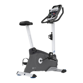
Nautilus U614 Service Manual
Hide thumbs
Also See for U614:
- Assembly manual / owner's manual (38 pages) ,
- Assembly manual / owner's manual (36 pages)
Advertisement
™
Table of Contents
Section Code
Section
1
1
1
1
Leveling the Machne
1
Moving the Machine
1
1
1
1
Replacement Procedure Skill Level
Mechanical Procedures
2
Belt Tension Adjustment
3
Set the Brake Tension (Calibration)
Part Replacement
4
Console
5
Pedals
6
Crank Arms - U616
7
Transport Wheels, Front Endcaps and Footpads
8
9
Handlebar Assembly
10
11
Data Cable in the Mast
12
13
14
Drive Belt and Flywheel Assembly
15
Belt Tensioner Assembly (Idler Assembly)
16
Drive Pulley Assembly (Crank Assembly) - U614
17
RPM Sensor (Speed Sensor)
18
Power Inlet
Nautilus, Inc., www.NautilusInc.com, 5415 Centerpoint Parkway, Groveport, OH 43125 U.S.A. - Customer Service: North America (800) 605-3369, csnls@nautilus.com | outside U.S.
www.nautilusinternational.com | © 2014 Nautilus, Inc. | Nautilus, the Nautilus logo, and Nautilus Trainer are trademarks owned by or licensed to Nautilus, Inc., which are registered or
otherwise protected by common law in the United States and other countries. Polar
owners. App Store is a service mark of Apple Inc. The Bluetooth
Inc. is under license.
8024421.081519.A
Nautilus
™
Upright Bikes Service Manual
word mark and logos are registered trademarks owned by Bluetooth SIG, Inc., and any use of such marks by Nautilus,
®
ORIGINAL DOCUMENT - ENGLISH VERSION ONLY
™
U614/U616 (Model Year 2014)
and U616 (Model Year 2017)
Page Number
2
3
4
5
5
6
8
10
12
13
13
16
19
19
21
23
27
29
34
37
41
44
46
50
53
55
58
60
, OwnCode
, Google Play™, Under Armour
®
®
1
Service Manual
and MyFitnessPal
are trademarks of their respective
®
®
8008057.081519.C
Advertisement
Table of Contents

Related Manuals for Nautilus U614


Summary of Contents for Nautilus U614
-
Page 1: Table Of Contents
Nautilus, Inc., www.NautilusInc.com, 5415 Centerpoint Parkway, Groveport, OH 43125 U.S.A. - Customer Service: North America (800) 605-3369, csnls@nautilus.com | outside U.S. www.nautilusinternational.com | © 2014 Nautilus, Inc. | Nautilus, the Nautilus logo, and Nautilus Trainer are trademarks owned by or licensed to Nautilus, Inc., which are registered or otherwise protected by common law in the United States and other countries. -
Page 2: Important Safety Instructions
Nautilus, Inc., www.NautilusInc.com, 5415 Centerpoint Parkway, Groveport, OH 43125 U.S.A. - Customer Service: North America (800) 605-3369, csnls@nautilus.com | outside U.S. www.nautilusinternational.com | © 2014 Nautilus, Inc. | Nautilus, the Nautilus logo, and Nautilus Trainer are trademarks owned by or licensed to Nautilus, Inc., which are registered or otherwise protected by common law in the United States and other countries. -
Page 3: Safety Warning Labels And Serial Number
Reading the Product Specification Decal The Manufacture Date on the Product Specification Decal is a date code: YY/WW (year/week). Specifications 300 lbs. (136 kg) Maximum User Weight: U614: 68.1 lbs. (30.9 kg) Machine Weight: U616: 68.6 lbs. (31.1 kg) Power Requirements (AC Adapter):... -
Page 4: Maintenance
FCC Compliance Changes or modifications to this unit not expressly approved by the party responsible for compliance could void the user’s authority to operate the equipment. The machine and power supply comply with part 15 of the FCC rules. Operation is subject to the following two conditions: (1) This device may not cause harmful interference, and (2) this device must accept any interference received, including interference that may cause undesired operation. - Page 5 Leveling Your Bike Levelers are found on each side of the Rear Stabilizer. Turn the stabilizer foot to adjust. Do not adjust the levelers to such a height that they detach or unscrew from the machine. Injury to you or damage to the machine can occur.
- Page 6 ® your results and share with friends and family. 1. Download the free Software App, named Nautilus Trainer™. The software app is available on the App Store and Google Play™. For a complete list of supported devices, review the software app on the App Store or Google Play™.
-
Page 7: Troubleshooting
Troubleshooting Condition/Problem Things to Check Solution No display/partial display/ Check electrical (wall) Make sure unit is plugged into a functioning wall outlet. unit will not turn on outlet Check connection on Connection should be secure and undamaged. Replace console adapter or connection at unit if either are damaged. Check data cable integrity All wires in cable should be intact. - Page 8 Condition/Problem Things to Check Solution Resistance does not Batteries (if equipped) Replace batteries and check for proper operation. change (machine turns on and operates) Check Console Check for visual sign that Console is damaged. Replace Con- sole if damaged. Check data cable integrity All wires in cable should be intact.
- Page 9 Contact appsupport@nautilus.com (if inside US/Canada) or your local distributor (if outside US/Canada) for further assistance. Workout results not post- Sync accounts From the Menu icon on the Nautilus Trainer™ App, select the ing from Nautilus Trainer ™ Sync to MyFitnessPal ®...
-
Page 10: Console Service Mode
Console Service Mode – x614 / x616 series (MY14) Consoles The Console Setup Mode lets you input the date and time, set the units of measurement to either English or Metric, change the machine type, control the sound settings ( on/ off), or see maintenance statistics (Total Run Hours – for service technician use only). - Page 11 All LEDs Off 1 second Sequence Segments 1 at a time – on 1 second, off 1 second Press any key to exit test h. RUN LCD TEST – Drives 3x5 and 1x5 LCD displays with the following patterns: All segments on All segments off Set individual segments one at a time until all segments are illuminated.
- Page 12 display shows an incorrect function, the overlay on the Console may be incorrect for that model. If the display Down). All LEDs On 1 second All segments on Set individual segments one at a time until all segments are illuminated. be reset to defaults.
-
Page 13: Maintenance Parts Exploded View
Maintenance Parts Exploded View Your machine may differ. Use only as a guide. U614 (MY14) Console HR Cable Flywheel Console Mast CHR Sensors Brake Assembly Pedals Seat RPM Sensor Crank Arms Seat Post w/ Slider Speed Sensor Magnet Left Shroud... - Page 14 U616 (MY14) Console HR Cable Flywheel Console Mast CHR Sensors Brake Assembly Pedals Seat RPM Sensor Crank Arms Seat Post w/ Slider Speed Sensor Magnet Left Shroud Adjustment Knob Servo Motor Power Inlet AC Adapter Drive Belt Right Shroud Water Bottle Holder Drive Pulley Top Shroud Rear Stabilizer...
- Page 15 U616 (MY17) Console HR Cable Flywheel Console Mast CHR Sensors Brake Assembly Pedals Seat RPM Sensor Crank Arms Seat Post w/ Slider Speed Sensor Magnet (8) Left Shroud Adjustment Knob Servo Motor Power Inlet AC Adapter Drive Belt Right Shroud Water Bottle Holder Drive Pulley Top Shroud...
- Page 16 REPLACEMENT PROCEDURE SKILL LEVEL Level I : Low - very little mechanical knowledge or exposure. Level II : Intermediate - some experience with mechanical procedures Level III : Advanced - knowledgeable about mechanical procedures When disposing of old parts, obey the applicable local and provincial requirements. For instructions to replace the following parts, please refer to the Assembly Manual for your bike: •...
- Page 17 Nautilus, Inc., www.NautilusInc.com, 5415 Centerpoint Parkway, Groveport, OH 43125 U.S.A. - Customer Service: North America (800) 605-3369, csnls@nautilus.com | outside U.S. www.nautilusinternational.com | © 2014 Nautilus, Inc. | Nautilus and the Nautilus logo are trademarks owned by or licensed to Nautilus, Inc., which are registered or otherwise protected by common law in the United States and other countries.
- Page 18 NOTICE: It is necessary to remove the Shrouds for this procedure. Refer to the “Replace the Shrouds” procedure. Disconnect all power to the machine before you service it. Note: Your machine may not match the image. For reference only. Figure 1 Remove the Top Shroud, Left Shroud and Right Shroud from the Main Unit.
- Page 19 NOTICE: Be sure not to crimp any cables. U614/R614 bikes—To reinstall the Pedals, carefully align the threads and hand tighten to prevent cross-threading. Then tighten fully with pedal wrench. Note: The Left Pedal is reverse-threaded. Orientation is based from a seated position on the bike. The Left Pedal has an “L”, the Right Pedal an “R”.
- Page 20 Nautilus, Inc., www.NautilusInc.com, 5415 Centerpoint Parkway, Groveport, OH 43125 U.S.A. - Customer Service: North America (800) 605-3369, csnls@nautilus.com | outside U.S. www.nautilusinternational.com | © 2014 Nautilus, Inc. | Nautilus and the Nautilus logo are trademarks owned by or licensed to Nautilus, Inc., which are registered or otherwise protected by common law in the United States and other countries.
- Page 21 NOTICE: It is necessary to remove the shrouds for this procedure. Refer to the “Replace the Shrouds” procedure. Note: Your machine may not match the image. For reference only. Disconnect and reconnect the AC Adapter from the wall outlet to turn the power off and on. Push QuickStart and verify that the console shows that the default resistance level is 4.
- Page 22 To adjust the Brake tension, loosen the 2 hex head bolts (C) and move the Servo Motor assembly (D) until the closest point on the Brake Magnet (A) is within 3.0 mm (1/8”) of the Flywheel (B). Tighten the bolts. Note: If the cardboard is not 3mm (1/8”) thick, you can use the pages of a paperback book to measure the gap.
- Page 23 Nautilus, Inc., www.NautilusInc.com, 5415 Centerpoint Parkway, Groveport, OH 43125 U.S.A. - Customer Service: North America (800) 605-3369, csnls@nautilus.com | outside U.S. www.nautilusinternational.com | © 2014 Nautilus, Inc. | Nautilus and the Nautilus logo are trademarks owned by or licensed to Nautilus, Inc., which are registered or otherwise protected by common law in the United States and other countries.
- Page 24 Disconnect all power to the machine before you service it. Note: Your machine may not match the image. For reference only. Remove screws that attach Console to the Mast. Carefully lift the Console off the Mast. Disconnect the Data Cable and Heart Rate Cable from the back of the Console.
- Page 25 Nautilus, Inc., www.NautilusInc.com, 5415 Centerpoint Parkway, Groveport, OH 43125 U.S.A. - Customer Service: North America (800) 605-3369, csnls@nautilus.com | outside U.S. www.nautilusinternational.com | © 2014 Nautilus, Inc. | Nautilus and the Nautilus logo are trademarks owned by or licensed to Nautilus, Inc., which are registered or otherwise protected by common law in the United States and other countries.
- Page 26 Note: Your machine may not match the image. For reference only. Loosen and remove the old Pedals. Discard the old Pedals. Note: The Left Pedal is reverse-threaded. Orientation is based from a seated position on the bike. The Left Pedal has an “L”, the Right Pedal an “R”.
- Page 27 Nautilus, Inc., www.NautilusInc.com, 5415 Centerpoint Parkway, Groveport, OH 43125 U.S.A. - Customer Service: North America (800) 605-3369, csnls@nautilus.com | outside U.S. www.nautilusinternational.com | © 2014 Nautilus, Inc. | Nautilus and the Nautilus logo are trademarks owned by or licensed to Nautilus, Inc., which are registered or otherwise protected by common law in the United States and other countries.
- Page 28 Note: Your machine may not match the image. For reference only. Loosen and remove the old Pedals. Set them safely aside for reassembly. Note: The Left Pedal is reverse-threaded. Orientation is based from a seated position on the bike. The Left Pedal has an “L”, the Right Pedal an “R”.
- Page 29 Thread the Crank Puller into the Crank Arm (B). When the Crank Puller is in the correct position, only 1-2 threads on the outer portion (CP2) of the Crank Puller should show. Note: with the Nut (CP2) as shown, before use. Using a wrench, turn the inner portion (CP3) of the Crank Puller clockwise.
- Page 30 Installation is the reverse procedure. Installation does not require the use of the crank puller. Be sure the Crank Arms are connected at 180° from each other. To reinstall the Pedals, carefully align the threads and hand tighten to prevent cross-threading. Then tighten fully with pedal wrench. Note: The Left Pedal is reverse-threaded.
- Page 31 Nautilus, Inc., www.NautilusInc.com, 5415 Centerpoint Parkway, Groveport, OH 43125 U.S.A. - Customer Service: North America (800) 605-3369, csnls@nautilus.com | outside U.S. www.nautilusinternational.com | © 2014 Nautilus, Inc. | Nautilus and the Nautilus logo are trademarks owned by or licensed to Nautilus, Inc., which are registered or otherwise protected by common law in the United States and other countries.
- Page 32 Note: Your machine may not match the image. For reference only. Place a static object (like a book or box) under the front stabilizer (C). The static object should not be compressible. Using a short #2 Phillips screwdriver, loosen and remove the screws (A1) from the Footpad (A), and set them safely aside.
- Page 33 Nautilus, Inc., www.NautilusInc.com, 5415 Centerpoint Parkway, Groveport, OH 43125 U.S.A. - Customer Service: North America (800) 605-3369, csnls@nautilus.com | outside U.S. www.nautilusinternational.com | © 2014 Nautilus, Inc. | Nautilus and the Nautilus logo are trademarks owned by or licensed to Nautilus, Inc., which are registered or otherwise protected by common law in the United States and other countries.
- Page 34 Disconnect all power to the machine before you service it. Note: Your machine may not match the image. For reference only. Remove the Seat Post and the Seat Adjustment Knob (A). Set them safely aside for reassembly. Your machine has one of these Crank configurations. Please use the images to select your configuration: 1-Piece Crank: 3-Piece Crank:...
- Page 35 Loosen and remove the Pedals. Set them safely aside for reassembly. Note: The Left Pedal is reverse-threaded. Orientation is based from a seated position on the bike. The Left Pedal has an “L”, the Right Pedal an “R”. Twist the Crank Cover (P) toward the front of the machine to disengage the inner tabs.
- Page 36 11. Using a #2 Phillips Screwdriver, remove the 6 screws (indicated) that secure the Left Shroud. Remove the bottom screws first, and then the top screws. Slowly remove the Left Shroud. Note: Find the Power Inlet (E) in the Left Shroud. Disconnect the Power Inlet cable (E1) from the wiring harness (F).
- Page 37 NOTICE: Be sure not to crimp any cables. Be sure the tabs in the Top Shroud snap into the Main Assembly. U614 bike—To reinstall the Pedals, carefully align the threads and hand tighten to prevent cross-threading. Then tighten fully with pedal wrench.
- Page 38 Nautilus, Inc., www.NautilusInc.com, 5415 Centerpoint Parkway, Groveport, OH 43125 U.S.A. - Customer Service: North America (800) 605-3369, csnls@nautilus.com | outside U.S. www.nautilusinternational.com | © 2014 Nautilus, Inc. | Nautilus and the Nautilus logo are trademarks owned by or licensed to Nautilus, Inc., which are registered or otherwise protected by common law in the United States and other countries.
- Page 39 Disconnect all power to the machine before you service it. Note: Your machine may not match the image. For reference only. Remove screws that attach Console to the Mast. Carefully lift the Console off the Mast. Disconnect the Data Cable and Heart Rate Cable from the back of the Console.
- Page 40 Remove the T-handle and washers that attach the Handlebar to the Mast. Set them safely aside for reassembly. NOTICE: Hold the Handlebar so that it does not fall. Untie the string from the HR Cable. Remove the old Handlebar and discard it. Put the replacement Handlebar in the bracket, adjust the Handlebar to the desired angle, and install the T-handle through the holes.
- Page 41 Nautilus, Inc., www.NautilusInc.com, 5415 Centerpoint Parkway, Groveport, OH 43125 U.S.A. - Customer Service: North America (800) 605-3369, csnls@nautilus.com | outside U.S. www.nautilusinternational.com | © 2014 Nautilus, Inc. | Nautilus and the Nautilus logo are trademarks owned by or licensed to Nautilus, Inc., which are registered or otherwise protected by common law in the United States and other countries.
- Page 42 Disconnect all power to the machine before you service it. Note: Your machine may not match the image. For reference only. Remove screws that attach Console to the Mast. Carefully lift the Console off the Mast. Disconnect the Data Cable and Heart Rate Cable from the back of the Console.
- Page 43 Remove the T-handle and washers that attach the Handlebar to the Mast. Set them safely aside for reassembly. NOTICE: Hold the Handlebar so that it does not fall. Remove the Handlebar and set it safely aside for reassembly. Remove the Mast Gasket. Remove the hardware (indicated) from the Mast.
- Page 44 10. Put the Handlebar in the bracket, adjust the Handlebar to the desired angle, and install the T-handle through the holes and washers. NOTICE: Do not crimp the cables. 11. Use the pull cable in the Handlebar Bracket to route the HR cable through the slot under the Handlebar Bracket to the top of the mast.
- Page 45 Nautilus, Inc., www.NautilusInc.com, 5415 Centerpoint Parkway, Groveport, OH 43125 U.S.A. - Customer Service: North America (800) 605-3369, csnls@nautilus.com | outside U.S. www.nautilusinternational.com | © 2014 Nautilus, Inc. | Nautilus and the Nautilus logo are trademarks owned by or licensed to Nautilus, Inc., which are registered or otherwise protected by common law in the United States and other countries.
- Page 46 Disconnect all power to the machine before you service it. Note: Your machine may not match the image. For reference only. Remove screws that attach Console to the Mast. Carefully lift the Console off the Mast. Disconnect the Data Cable and Heart Rate Cable from the back of the Console.
- Page 47 Tie the length of string to the end (A) of the Data Cable at the base of the Mast. Hold the other end of the Data Cable (B) and carefully pull it out of the Mast so that the string extends through the length of the Mast.
- Page 48 Nautilus, Inc., www.NautilusInc.com, 5415 Centerpoint Parkway, Groveport, OH 43125 U.S.A. - Customer Service: North America (800) 605-3369, csnls@nautilus.com | outside U.S. www.nautilusinternational.com | © 2014 Nautilus, Inc. | Nautilus and the Nautilus logo are trademarks owned by or licensed to Nautilus, Inc., which are registered or otherwise protected by common law in the United States and other countries.
- Page 49 NOTICE: It is necessary to remove the Shrouds for this procedure. Refer to the “Replace the Shrouds” procedure. It may be necessary to adjust the Brake tension at the end of this procedure. Refer to the “Set the Brake Tension” procedure. Disconnect all power to the machine before you service it.
- Page 50 Nautilus, Inc., www.NautilusInc.com, 5415 Centerpoint Parkway, Groveport, OH 43125 U.S.A. - Customer Service: North America (800) 605-3369, csnls@nautilus.com | outside U.S. www.nautilusinternational.com | © 2014 Nautilus, Inc. | Nautilus and the Nautilus logo are trademarks owned by or licensed to Nautilus, Inc., which are registered or otherwise protected by common law in the United States and other countries.
- Page 51 NOTICE: It is necessary to remove the Shrouds for this procedure. Refer to the “Replace the Shrouds” procedure. It may be necessary to adjust the Brake tension at the end of this procedure. Refer to the “Set the Brake Tension” procedure. Disconnect all power to the machine before you service it.
- Page 52 Observe the cable routing. Disconnect the Speed Sensor Cable (D) and Power Inlet Cable (E) from the wiring harness (F). Tie the length of string to the end of the lower Console Cable (G) at the top of the Mast mount. Pull the cable and string down through the hole (H) at the base of the Mast so that the string extends through the mast.
- Page 53 13. Reinstall the Mast, Console, Mast Gasket and Top Shroud. (Refer to the “Replace the Shrouds” procedure.) Turn the power on. Machine is on. Current is active. There is risk of electrical shock. 14. Use the console to set the resistance to the highest level. Unplug the machine.
- Page 54 Nautilus, Inc., www.NautilusInc.com, 5415 Centerpoint Parkway, Groveport, OH 43125 U.S.A. - Customer Service: North America (800) 605-3369, csnls@nautilus.com | outside U.S. www.nautilusinternational.com | © 2014 Nautilus, Inc. | Nautilus and the Nautilus logo are trademarks owned by or licensed to Nautilus, Inc., which are registered or otherwise protected by common law in the United States and other countries.
- Page 55 NOTICE: It is necessary to remove the Shrouds for this procedure. Refer to the “Replace the Shrouds” procedure. It is necessary to adjust the Drive Belt tension at the end of this procedure. Refer to the “Belt Tension Adjustment” procedure Disconnect all power to the machine before you service it.
- Page 56 Using needlenose pliers, carefully release the spring (E1) on the Belt Tensioner (E). To remove the hardware from the Flywheel (C), use the 15 mm open end wrench to hold the nut (F) on one side steady and remove the nut on the opposite side with the 15 mm socket and wrench.
- Page 57 Nautilus, Inc., www.NautilusInc.com, 5415 Centerpoint Parkway, Groveport, OH 43125 U.S.A. - Customer Service: North America (800) 605-3369, csnls@nautilus.com | outside U.S. www.nautilusinternational.com | © 2014 Nautilus, Inc. | Nautilus and the Nautilus logo are trademarks owned by or licensed to Nautilus, Inc., which are registered or otherwise protected by common law in the United States and other countries.
- Page 58 NOTICE: It is necessary to remove the Shrouds for this procedure. Refer to the “Replace the Shrouds” procedure. It is necessary to adjust the Drive Belt tension at the end of this procedure. Refer to the “Belt Tension Adjustment” procedure Disconnect all power to the machine before you service it.
- Page 59 Nautilus, Inc., www.NautilusInc.com, 5415 Centerpoint Parkway, Groveport, OH 43125 U.S.A. - Customer Service: North America (800) 605-3369, csnls@nautilus.com | outside U.S. www.nautilusinternational.com | © 2014 Nautilus, Inc. | Nautilus and the Nautilus logo are trademarks owned by or licensed to Nautilus, Inc., which are registered or otherwise protected by common law in the United States and other countries.
- Page 60 NOTICE: It is necessary to remove the Shrouds for this procedure. Refer to the “Replace the Shrouds” procedure. It is necessary to adjust the Drive Belt tension at the end of this procedure. Refer to the “Belt Tension Adjustment” procedure Disconnect all power to the machine before you service it.
- Page 61 Carefully pull the Pulley Shaft Assembly (H) until it works out of the Frame and releases the Washer (J), Bumper (K), Bearings (L) and Bearing Brackets (M). Installation is the reverse procedure. NOTICE: Do not overtighten the crank hardware as this can damage the bearings.
- Page 62 Nautilus, Inc., www.NautilusInc.com, 5415 Centerpoint Parkway, Groveport, OH 43125 U.S.A. - Customer Service: North America (800) 605-3369, csnls@nautilus.com | outside U.S. www.nautilusinternational.com | © 2014 Nautilus, Inc. | Nautilus and the Nautilus logo are trademarks owned by or licensed to Nautilus, Inc., which are registered or otherwise protected by common law in the United States and other countries.
- Page 63 NOTICE: It is necessary to remove the Shrouds for this procedure. Refer to the “Replace the Shrouds” procedure. Disconnect all power to the machine before you service it. Note: Your machine may not match the image. For reference only. Carefully remove the Shrouds. Refer to the “Replace the Shrouds” procedure in this manual.
- Page 64 Nautilus, Inc., www.NautilusInc.com, 5415 Centerpoint Parkway, Groveport, OH 43125 U.S.A. - Customer Service: North America (800) 605-3369, csnls@nautilus.com | outside U.S. www.nautilusinternational.com | © 2014 Nautilus, Inc. | Nautilus and the Nautilus logo are trademarks owned by or licensed to Nautilus, Inc., which are registered or otherwise protected by common law in the United States and other countries.
- Page 65 NOTICE: It is necessary to remove the Shrouds for this procedure. Refer to the “Replace the Shrouds” procedure. Disconnect all power to the machine before you service it. Note: Your machine may not match the image. For reference only. Carefully remove the Left Shroud. Refer to the “Replace the Shrouds” procedure in this manual.
- Page 66 Loosen and remove the thin Nut from the Power Inlet (C) on the outside of the Shroud. Pull the Power Inlet plug (C) out of the hole toward the inside of the Shroud. Discard the old Power Inlet assembly. Installation is the reverse procedure. NOTICE: Do not crimp any cables.
Need help?
Do you have a question about the U614 and is the answer not in the manual?
Questions and answers