Advertisement
Quick Links
Advertisement

Related Manuals for FAAC Estate Swing E-SC 1102 Series


Summary of Contents for FAAC Estate Swing E-SC 1102 Series
- Page 1 1102 Series Manufactured by...
- Page 2 Address: Via Benini, 1 – 40069 Zola Predosa Bologna – Italy Declares that: Domolink A.K.A. Estate Swing (USA) mod operator Is built to be integrated into a machine or to be assembled with other machinery to create a machine under the provisions •...
- Page 3 Estate Swing Summery of Functions The Estate Swing is only to be used for vehicular swing gates in a Class I setting. Class I: A vehicular gate opener (or system) intended for use in a home of one-to-four single family dwelling, or a garage or parking area associated therewith.
-
Page 4: Mounting Control Box
Review of specifications, warnings, parts, and tools • Specifications of the Estate Swing and Components ⇒ System Overview & Preliminary Checks ⇒ Estate Swing Parts List ⇒... -
Page 5: Diagnostics And Troubleshooting
The table of contents are listed to assist you locating a desired section. We do how- ever strongly suggest studying every page of the instruction manual before at- tempting installation. Diagnostics & Troubleshooting • Simple Diagnostics ⇒ Trouble Shooting ⇒ Logic Summaries and Flow Charts ⇒... - Page 6 Operating ambient temperature Operator weight (lbs) Protection class Gate leaf max length (ft.) Gate leaf max weight (lbs.) Operator overall dimensions LxHxD(in.) Estate Swing 115V AC/ 12V DC 1700 1.25 2.3 CANNOT BE MODIFIED Max. 15 10 min. for each full cycle -4 to 131 Deg F 4.85...
- Page 7 The fence post must be secured in the ground with concrete. This will prevent • alteration of alignments and leveling during installation and during cycles. 1,2 Estate Swing Operator 3 Photocells (not included) 4 Master control board 5 Slave control board...
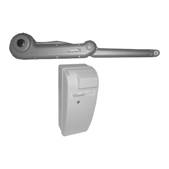
- Page 8 A. Control Box B. Operator Arm C. Gate Mount Bracket D. Post Mount Brackets E. Transmitter F. Receiver G. Post Mounting nuts, Manual Release Key H. Transformer A. Control Box B. Operator Arm C. Gate Mount Bracket D. Post Mount Brackets G.
- Page 9 Other items that may be needed prior to commencing installation. Bolded items are necessary to all applications. Start and stop post, bracket or door stop. Although the FAAC Estate swing features soft start/ • stop it is still recommended to have a closed stop post because having a start and stop point per- manently in place may extend the life of the operator by absorbing some of the momentum of the gate during open and close cycles.
- Page 10 ATTENTION: Study the control board and read this section thoroughly before attempting to operate your gate opener. Warnings: Before attempting any job on the control board (connections, maintenance), turn • off electrical power and unplug the support battery. Install a surge protector upstream of your opener, the opener is not power surge •...
-
Page 11: Continued On Next Page
Before beginning any electrical stages of installation we highly recommend charg- ing the battery on the control board for 12 hours. This can be done anywhere there is an outlet available. 1. Plug the battery into the control board (fig 1). For charg- ing purposes it is not necessary to hook the receiver to the battery or control board. - Page 12 Charge the slave board by wiring it to the master board terminal strip. [terminal 6 of the master must connect with the right side of J2 on the slave and terminal 15 of the master must connect with the left side of the slave] (fig 3) NEVER CONNECT POWER FROM ANY SOURCE DIRECTLY TO THE SLAVE BOARD.
- Page 13 The setback is a very important requirement to be aware of during installation of the post mounting bracket. The setback allows the operator arm to achieve appropriate and equal leverage during opening and closing cycles. 1 1/4” - 6 1/3” 4” - 6 1/3” 6 1/3”...
- Page 14 1. Set up closed stop points for your gates if you are choosing to use them. For a snug closing the master gate should close against the slave gate using an overlapping bracket as in the picture to the right. The closed stop on the ground is for an overall taught closing point 3.
- Page 15 4. Using a tape measure, snap line or some- thing else straight, draw a line where the full closed point of the gates will be. Then from the center of that line measure in towards the prop- erty 1 inch. This will be where the arms in the fully extended position will mount to the gate.
- Page 16 (fig 2). Fig 1 Fig 2 Your box must be kept water- tight. Moisture can damage your control board. If you have trouble locating a water- tight connector contact Estate Swing 1-800-640-GATE for assistance.
-
Page 17: For Your Convenience
For Your Convenience The green numbered terminal strip at the bottom of the control board is easily removed for wiring. Simply pull straight down on the terminal strip to remove it from the board. It will slide right off. Slide it back on when you are finished with your wiring connections. - Page 18 For your opener to function properly a few connections must be made prior to the learning process. Accessories should NOT be installed until after the learn- ing process is completed. Using the provided jumper wire, connect the normally closed safety terminals (terminals 3, 4, and 5) to one of the negative terminals (terminals 12, 13, 14, or 15).
- Page 19 Slave Board Power— On the slave board it is used as communication with the master board and powering from the master board. Connect the slave board to the master board using 16 gauge low voltage wire. This wire must be run across the drive- way and can be up to 100 feet in length.
- Page 20 Installing the Receiver 1) Locate the 5 Silver Pins on your MASTER Estate Swing board, located above the battery. 2) Locate the white connector on the receiver. 3) Push the white connector from the receiver on the 5 pins on your FAAC board with the dip switches of the receiver board facing away from the center of the Estate Swing board.
-
Page 21: Battery Input
1. The Estate Swing (Master Unit if Dual Operator) comes with 1) AC transformer. The AC transformer supplied has 4 screw terminals, use the center 2 terminals to attach your low voltage wire (polarity is not relevant). You may locate the transformer up to 1000’... - Page 22 Using the following procedures you can change factory settings such as auto close, speed, force, delays and more. results providing increased safety, convenience or other. B: Switches between the amount of time the gate pauses before closing after reaching full open.
- Page 23 It has an increased amount of motion stop points.) 4= EP (Stepped Semi-automatic - is designed to function similar to a garage door opener. Turns off the auto close setting.) Pause Times 1= 5 Seconds...
- Page 24 Begin by pressing P1 6 times to light A-E simultaneously. While the 5 LEDs are lit steadily, hold down P2 for about 3 seconds. The operator will start the maneuver process. Using P2, Briefly press the button once for each of the following motion transitions: Let the leaf make contact with the full open stop point.
- Page 25 Let the leaf make contact with the full open stop point. The opener will then stop and reverse directions. OR if not using open stops 4 alt.) Press P2 to stop the openers opening motion and reverse the motion of the gate. Press P2 to teach leaf 2 opening decelera- tion starting point.
- Page 26 Let the leaf 2 make contact with the full closed stop point or full closing point of arm. Leaf 1 will begin closing. Let the leaf 1 make contact with the full closed stop point or full closing point Press to exit the learning mode.
- Page 27 Status of accessory inputs. The Master Control Board has the ability to verify the status of the terminal board inputs. To ac- cess this function: When all LEDs are off (both lettered and numbered) press P2. The statuses of the accessory ter- minals in the following chart will be shown in the lettered LEDs column.
- Page 28 Gate Crafters and FAAC, if you choose to only use the inher- ent obstruction sensing featured in the Estate Swing control board you must con- nect terminals 3, 4, 5 to a negative terminal (12, 13, 14, or 15).
- Page 29 If the power LED (P) is flashing slowly. This means your main power is not on, the battery is low and absorbing too much of the main • power, or the main power was plugged in for less than 5 minutes. Be sure before installation the battery is charged for 12 hours.
- Page 30 Re-program the gate in Com- plete Stop/Start Learning Process (Section 20). Check the setback. This is very important for the memory process. • For any technical assistance Estate Swing can be reached 9 AM to 5 PM, Monday - Friday. 1-800-640-GATE...
- Page 31 If you call in for technical support or warranty support: before any control board or motor will be permitted to be sent in for testing or warranty you will be required to e-mail digital photos to the technician. This is done in your best interest to save unnecessary shipping expenses and time lost. Many times we can come up with solutions to issues by seeing pictures that relay information that is impossible to relay through a phone conversation.
- Page 32 Logic A - Logic A (automatic) is the most common setting. It automatically closes the gate de- pending on the set pause time. This logic must be used in conjunction with the accessories: Free Exit Sensor and Gate Timer. Gate Status Gate Status Result of Termi- Result of Terminal...
- Page 33 Logic AP - Logic AP (stepped automatic) is very similar to automatic (A) but has a higher amount of safety. It has an increased amount of motion stop points. Gate Status Gate Status Result of Termi- Result of Terminal Result of Termi- nal 1 activation 1 activation nal 2 activation...
- Page 34 Normally Closed connections must be made for proper gate opener function. The full accessory board is only found on the master control board. J1—Terminal Board for Master Card Terminals 1 - “Open/Close Function” This is a normally open terminal where by any device (i.e. push button, keypad, receiver) which, by closing a contact, provides an opening and/or clos- ing pulse for both gate leaves (if there is only one leaf, it will control the one leaf).
- Page 35 J1—Terminal Board for Master Card (cont.) Terminals (cont.) 5 - “Closing Safety Device” This is a normally closed terminal where by any device (i.e. photocells, sensitive edge, magnetic loops) which, if there is an obstacle in the area they protect during closing, reverses gate direction to opening. If the closing safety devices are tripped when the gate is open, they prevent the leaf movement.
- Page 36 Before connecting the photocells (or other devices) we advise you to select the type of operation according to the movement zone to be protected. Opening Safety Devices: They operate only during the gate opening movement and, therefore, they are suitable for protecting the zone between the opening leaves and fixed obstacles (walls, etc.) against...
- Page 38 The accessory manuals you have or find at the above address may be written to coincide with that manufacturers model of gate opener. To determine correct terminals on your Estate Swing operator, use the accessory terminal section of your Estate Swing manual. The following are some common terms and abbreviations found in manuals: Normally Open –...
Need help?
Do you have a question about the Estate Swing E-SC 1102 Series and is the answer not in the manual?
Questions and answers