Table of Contents
Advertisement
Advertisement
Table of Contents

Related Manuals for FAAC C850


Summary of Contents for FAAC C850
- Page 1 C850 C850...
-
Page 2: Control Board
• conforms to the essential safety requirements of the following EEC directives: 2006/95/EC Low Voltage Directive 2004/108/EC Electromagnetic Compatibility Directive Additional information: This product underwent a test in a typical uniform confi guration (all products manufactured by FAAC S.p.A.). Bologna, 01-01-2012 The Managing Director A. Marcellan C850... - Page 3 17) Use of at least one indicator-light (e.g. FAACLIGHT ) is recommended 6) FAAC declines all liability caused by improper use or use other than for every system, as well as a warning sign adequately secured to the that for which the automated system was intended.
-
Page 4: Table Of Contents
12 OMRON INVERTER CONTROL UNIT ......................28 12.1 DESCRIPTION OF THE INVERTER CONTROL PANEL .................28 12.2 PROGRAMMING THE INVERTER ........................30 12.3 12.3 INVERTER DEFAULTS ..........................31 12.4 INVERTER ERROR ............................33 12.5 OPTIONAL ACCESSORIES ..........................34 12.5.1 EXTERNAL PROGRAMMING KEYBOARD ......................34 C850 532015 - Rev.B... -
Page 5: General
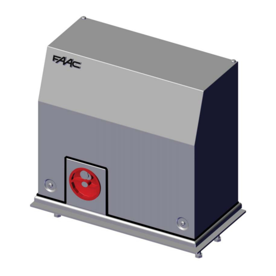
These instructions apply to the following models: C850 The C850 is an electromechanical operator designed for moving sliding gates. The non-reversing system is guaranteed by an electric brake that prevents manual movement of the sliding leaf when the motor is stopped, and therefore does not require an electric lock. -
Page 6: Dimensions
If the gearmotor is exposed to vehicle transit, provide for adequate protection against accidental impact, when possible. • Ensure that there is an efficient earth plate for connecting the gearmotor. Should the various elements not meet the above-mentioned conditions, adjust them so they do. C850 532015 - Rev.B... -
Page 7: Walling In The Foundation Plate
Prepare the electrical cables for connecting the accessories and the electrical power, as shown in Fig. 3. To facilitate connection to the control unit, pull out a stretch of cable measuring at least 1.5 m from the hole on the plate. Dimensions in mm Fig. 7 C850 532015 - Rev.B... -
Page 8: Mechanical Installation
(Fig. 9 ref. Use the adjustment screws to set the height of the gearmotor (Fig. 10 ref. ), referring to the measurements in Fig. 12. Fig. 11 Fig. 12 Fig. 9 C850 532015 - Rev.B... -
Page 9: Installing The Rack
Manually move the gate and weld the three threaded pawls, con- Manually move the gate and, as for the first element, proceed with tinuing until the gate is completely covered. securing until the gate is completely covered. Fig. 13 Fig. 14 Fig. 15 Fig. 16 C850 532015 - Rev.B... -
Page 10: Operation
) and protected by a cover (Fig. 19 ref. To correctly connect and program the control unit, remove the cover and follow the instructions in section 11 (E850 Electronic Control Unit). Fig. 19 Dimensions in mm Fig. 17 C850 C850 532015 - Rev.B... -
Page 11: Final Adjustment Of The Limit Switches
13. In chart 2, knowing the weight and the operating speed of the sliding leaf, calculate the corresponding DECELERATION TIME t[s]. DECELERATION TIME Chart 2 Example: P = 1000 Kg V = 0.6 m/sec t = 1.7 sec C850 532015 - Rev.B... - Page 12 Right to Left. FCO = opening limit switch (screw FCC = closing limit switch (screw ROP = start of opening deceleration (screw RCL = start of closing deceleration (screw Fig. 20 Fig. 21 Fig. 22 C850 532015 - Rev.B...
-
Page 13: Testing The Automated System
10 REPAIRS To release the gearmotor, proceed as follows: For repairs, contact an authorised FAAC Service Centre. Insert the provided key and turn clockwise (Fig. 24 ref. Turn the release system clockwise until it reaches the mechanical stop (Fig. -
Page 14: E850 Electronic Control Unit
LOW-VOLTAGE AND ACCESSORIES FUSE (T 800mA) 5-pin board connector for Minidec, “F” PROGRAMMING BUTTON Rapid connector Decoder, RP/RP2 Receiver “+” PROGRAMMING BUTTON “-” PROGRAMMING BUTTON Multi-function display, BUS technology and Characteristics INTEGRATED METAL MASS DETECTOR TRANSFORMER C850 532015 - Rev.B... -
Page 15: Electrical Connections
OUT 4 - Output 4 open-collector +24 VDC (terminal 18): the output can be set in one of the functions described in Advanced Pro- gramming Level (par. 11.5.2.). The default value for ALL PRE-SETTINGS is BUS COMMUNICATION. Maximum load: 24 VDC with 100 mA. C850 532015 - Rev.B... -
Page 16: Photocell Connection To Relays And Safety Devices With "N.c." Contact
Pair of Photocells Pairs of photocells for OPEN pulse: max 1 BUS BUS BUS BUS RX - TX Pair of Photocells BUS BUS BUS BUS RX - TX BUS BUS BUS BUS Fig. 32 Fig. 33 C850 532015 - Rev.B... -
Page 17: Terminal Board J2, Flashing Lamp (Fig.28)
L: 230 V~ or 115 V~ Power supply (Line) For correct operation, you must connect the board to the system’s earth conductor. Ensu- re that a suitable differential magnetothermic switch has been installed upstream. E850 E850 Fig. 35 C850 532015 - Rev.B... - Page 18 LEFT-HAND opening, the connections will be inverted on site, as shown in figures 36 and 37. Fig. 36 GATE WITH RIGHT-HAND OPENING (DEFAULT) GATE WITH LEFT-HAND OPENING OMRON INVERTER OMRON INVERTER E850 E850 GREY GREY FCC-FCO FCC-FCO PINK PINK WHITE GREEN BROWN YELLOW GREEN WHITE YELLOW BROWN C850 532015 - Rev.B...
- Page 19 Fig. 37 ³ · RIGHT-HAND OPENING (DEFAULT) » ¿ LEFT-HAND OPENING C850 532015 - Rev.B...
-
Page 20: Programming
Default Regulates the sensitivity of the loop = minimum PARAMETER LOADING: Neutral condition = maximum FAAC 1 Default loaded AUTOMATED SYSTEM STATUS: Exit programming, store settings and return to automated system LEAVE ON IF YOU DO NOT WISH TO status display. -
Page 21: Changing The Pre-Settings
If once the entry is completed there are NO BUS devices, the EXAMPLE: by selecting and exiting the basic programming level, all FAAC production values are loaded and can be found in display will go back to the BASIC, ADVANCED AND EXPERT level tables in the “Default”... -
Page 22: Advanced Programming Level
=FCC engaged =Leaf opening =Leaf closing OUTPUT 1 POLARITY: Lets you confi gure the output polarity. = N.C. polarity = N.O. polarity Note: if the output is set as FAIL-SAFE ( leave the value on “no”. C850 532015 - Rev.B... -
Page 23: Setting The Integrated Loop Detector
3 m LOOP 1 LOOP 2 from 3 to 4 m from 4 to 6 m from 6 to 12 m more than Decimal point FLASHING = Loop NOT CONNECTED or 12 m CALIBRATING Fig. 44 C850 532015 - Rev.B... -
Page 24: Expert Programming Level
OPEN has priority over CLOSE. = disabled When this function is activated, the CLOSE command commands closing when released. = closes when released As long as CLOSE is activated, the unit stays in closing pre-fl ashing mode. = closes immediately C850 532015 - Rev.B... -
Page 25: Personalising The Operating Logic
Select the basic logic that most suits your needs. Enter the expert programming level and change the desired parameters. Exit expert level from the basic level and select the logic The logic activates the changes made at expert level. C850 532015 - Rev.B... -
Page 26: 11.9 Operating Logics Tables
(OPEN/CLOSE (OPEN stops - STOPPED direction. After STOP (OPEN disabled) (OPEN disabled) disabled) CLOSE is stored) always closes In brackets, the effects on the other inputs when the pulse is active. C850 532015 - Rev.B... - Page 27 (OPEN/CLOSE (OPEN/CLOSE STOPPED (OPEN disabled) (CLOSE disabled) disabled) disabled) In brackets, the effects on the other inputs when the pulse is active. C850 532015 - Rev.B...
-
Page 28: Omron Inverter Control Unit
(Ensure that the RUN command LED is on) Forward/Back RUN key F004 rotation depends on the setting of “ ” Reduces the speed and stops the inverter. Same function as the RESET key when STOP/RESET key there is an inverter fault. C850 532015 - Rev.B... - Page 29 Do not press Enter if you do not wish to store changes (e.g. when a change is made inadvertently). Changes the mode. Increase key Also, it increases the set value of each function. Changes the mode. Decrease key Also, it decreases the set value of each function. C850 532015 - Rev.B...
-
Page 30: Programming The Inverter
WARNING: DO NOT CHANGE parameters other than those indicated in this section. • press the YELLOW button to confirm; Incorrect changes can be dangerous for people, things or the C850 motor. • to exit programming, press the BLUE button for 5 d001 sec, until appears;... -
Page 31: Inverter Defaults
“No stop in case of temporary power PID P Gain A072 b050 interruption function selection” PID I Gain A073 “No start-up voltage stop in case of b051 PID D Gain 0.00 A074 temporary power interruption function” C850 532015 - Rev.B... - Page 32 7.10 C039 Overload warning level 7.10 C041 Arrival frequency during acceleration C042 Arrival frequency during deceleration C043 PID excessive deviation limit C044 PID FB upper limit 100.0 C052 PID FB lower limit C053 Operator/Modbus selection C070 C850 532015 - Rev.B...
-
Page 33: Inverter Error
Check the DECELERATION set in the parameter F003, as shown in section 6.2 FINAL ADJUSTMENT OF THE LIMIT SWITCHES, paragraphs 13 and 14, and, if necessary, increase the deceleration value. NOTE: In case of other ERROR warnings, wait (10 sec) for the inverter to reset automatically. If the ERROR persists, press STOP/RESET C850 532015 - Rev.B... -
Page 34: Optional Accessories
The keyboard memory lets you save and store up to 4 customised programming settings, made available for future use. The keyboard features an LCD display (Fig. 47). For complete keyboard functions, see the dedicated instructions. Abb. 47 C850 532015 - Rev.B... - Page 35 A stop pulse (if provided) always stops movement. The light signalling indicates that the gate is currently moving. GENERAL SAFETY RULES If installed and used correctly, the C850 automated system will For details on sliding gate behaviour in different function logics, ensure a high degree of safety.
- Page 40 POLAND Saint Priest, Lyon - France FAAC POLSKA SP.ZO.O tel. +33 4 72218700 Warszawa - Poland www.faac.fr tel. +48 22 8141422 FAAC FRANCE - AGENCE PARIS www.faac.pl Massy, Paris - France RUSSIA tel. +33 1 69191620 FAAC RUSSIA LLC www.faac.fr...
Need help?
Do you have a question about the C850 and is the answer not in the manual?
Questions and answers