Table of Contents
Advertisement
Quick Links
EC DECLARATION OF CONFORMITY FOR MACHINES
Manufacturer:
FAAC S.p.A.
Address:
Via Benini, 1 - 40069 Zola Predosa BOLOGNA - ITALY
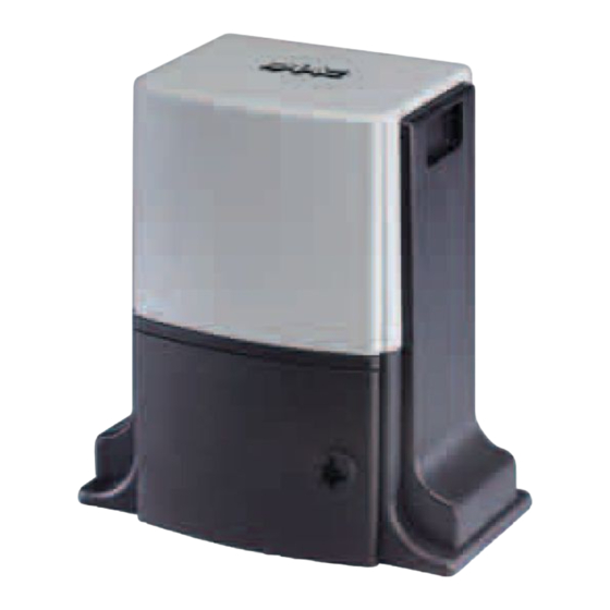
DOMOGLIDE-B7 mod. operator
Declares that:
• is built to be integrated into a machine or to be assembled with other machinery to create a machine under the
provisions of Directive 98/37/EC;
• conforms to the essential safety requirements of the following EEC directives:
73/23/EEC and subsequent amendment 93/68/EEC.
89/336/EEC and subsequent amendment 92/31/EEC and 93/68/EEC
and also declares that it is prohibited to put into service the machinery until the machine in which it will be integrated or of
which it will become a component has been identified and declared as conforming to the cond
EC.
Bologna, 01-07-2005
1) ATTENTION! To ensure the safety of people, it is important that you read
all the following instructions. Incorrect installation or incorrect use of the
product could cause serious harm to people.
2) Carefully read the instructions before beginning to install the product.
3) Do not leave packing materials (plastic, polystyrene, etc.) within reach of
children as such materials are potential sources of danger.
4) Store these instructions for future reference.
5) This product was designed and built strictly for the use indicated in this
documentation. Any other use, not expressly indicated here, could compro-
mise the good condition/operation of the product and/or be a source of
danger.
6) FAAC declines all liability caused by improper use or use other than that for
which the automated system was intended.
7) Do not install the equipment in an explosive atmosphere: the presence of
inflammable gas or fumes is a serious danger to safety.
8) The mechanical parts must conform to the provisions of Standards EN 12604
and EN 12605.
For non-EU countries, to obtain an adequate level of safety, the Standards
mentioned above must be observed, in addition to national legal regulations.
9) FAAC is not responsible for failure to observe Good Technique in the
construction of the closing elements to be motorised, or for any deformation
that may occur during use.
10) The installation must conform to Standards EN 12453 and EN 12445.
For non-EU countries, to obtain an adequate level of safety, the Standards
mentioned above must be observed, in addition to national legal regulations.
11) Before attempting any job on the system, cut out electrical power and
disconnect the batteries.
12) The mains power supply of the automated system must be fitted with an all-
pole switch with contact opening distance of 3mm or greater. Use of a 6A
thermal breaker with all-pole circuit break is recommended.
13) Make sure that a differential switch with threshold of 0.03 A is fitted upstream
of the system.
14) Make sure that the earthing system is perfectly constructed, and connect
(DIRECTIVE 98/37/EC)
Warnings FOR THE INSTALLER
GENERAL SAFETY OBLIGATIONS
19
The Managing Director
metal parts of the means of the closure to it.
15) The automated system is supplied with an intrinsic anti-crushing safety device
consisting of a torque control. Nevertheless, its tripping threshold must be
checked as specified in the Standards indicated at point 10.
16) The safety devices (EN 12978 standard) protect any danger areas against
mechanical movement Risks, such as crushing, dragging, and shearing.
17) Use of at least one indicator-light (e.g. FAACLIGHT 12VDC) is recommended
for every system, as well as a warning sign adequately secured to the frame
structure, in addition to the devices mentioned at point "16".
18) FAAC declines all liability as concerns safety and efficient operation of the
automated system, if system components not produced by FAAC are used.
19) For maintenance, strictly use original parts by FAAC.
20) Do not in any way modify the components of the automated system.
21) The installer shall supply all information concerning manual operation of the
system in case of an emergency, and shall hand over to the user the warnings
handbook supplied with the product.
22) Do not allow children or adults to stay near the product while it is operating.
23) Keep remote controls or other pulse generators away from children, to
prevent the automated system from being activated involuntarily.
24) Transit is permitted only when the automated system is idle.
25) The user must not attempt any kind of repair or direct action whatever and
contact qualified personnel only.
26) Do not short-circuit the poles of the batteries and do not try to recharge the
batteries with power supply units other than those provided with the
equipment.
27) Do not throw exhausted batteries into containers for other waste but dispose
of them in the appropriate containers to enable them to be recycled. Disposal
costs have already been paid for by the manufacturer.
28) Maintenance: check at least every 6 months the efficiency of the system,
particularly the efficiency of the safety devices (including, where foreseen,
the operator thrust force) and of the release devices.
29) Anything not expressly specified in these instructions is not permitted.
itions of Directive 98/37/
A. Bassi
Advertisement
Table of Contents

Related Manuals for FAAC DOMOGLIDE-B7


Summary of Contents for FAAC DOMOGLIDE-B7
- Page 1 FAAC are used. 6) FAAC declines all liability caused by improper use or use other than that for 19) For maintenance, strictly use original parts by FAAC. which the automated system was intended.
- Page 2 Notes on DOMOGLIDE-B7 work batteries The battery supplied with the DOMOGLIDE-B7 operator is a WORK BATTERY which directly powers the automated system. It is not a back-up battery. The battery is recharged by the control board to which it is connected via a transformer and a specific integrated circuit. Bear in mind that it takes about 10 to 20 minutes of recharging to recover the energy used during an opening/closing cycle (this value varies according to operating ambient temperature, battery life and type of system).
- Page 3 DOMOGLIDE-B7 automated system These instructions apply to the following model: Tab. 1 - Technical specifications of DOMOGLIDE-B7 operator FAAC DOMOGLIDE-B7 The DOMOGLIDE-B7 automated system automates residential sliding gates with leaves of up to 5 m in length and 300 kg in weight.
- Page 4 12 Vdc flashing lamp Receiver Closing stop Upper track Key operated push- button Rx Photocell Tx photocell Opening stop DOMOGLIDE-B7 operator Differential thermal breaker Fig. 3 3 x 0,5 2 x 0,75 3 x 0,5 3 x 0,5 2 x 0,5 3 x 1.5 (2 + T) for 230Vac or 2 x...
- Page 5 4. INSTALLING THE AUTOMATED SYSTEM Closing dir. 4.1. Preliminary checks To ensure safety and an efficiently operating automated system, make sure the following conditions are observed: • The structure of the gate must be suitable for being automated. In particular, check that the structure is sufficiently strong and rigid, and that its dimensions and weight conform to those indicated in the technical specifications.
- Page 6 4.4. Positioning the operator 4.6. Securing the operator • Lay the electric cables for connection to the accessories and • Temporarily fix the operator by slightly tightening the screws power supply as shown in Fig. 4. To facilitate making the as shown in Fig.
- Page 7 4.8. Installing the rack 4.8.1. Steel rack to be welded (Fig. 13) 1) Place the three threaded pawls on the rack element, positioning them at the top of the slot. In this way, the slot play will enable any adjustments to be made. 2) Manually take the gate into its closing position.
- Page 8 Notes on rack installation • Make sure that, during the gate travel, all the rack elements mesh correctly with the pinion. • Do not, on any account, weld the rack elements either to the spacers or to each other. • When you have finished installing the rack, adjust the distance between the pinion teeth and the rack groove, checking if the distance is 2.5 mm (Fig.
- Page 9 CONTROL BOARD WARNINGS Attention: Before attempting any job on the control board (connections, maintenance), cut out electric power and the battery. - Install, upstream of the system, a differential thermal breaker with adequate tripping threshold. - Always separate 230VAC power cable from control and safety cables (push-buttons, receiver, photocells, etc.). To avoid any electric noise, use separate sheaths or a shielded cable (with earthed shield).
- Page 10 7. ELECTRICAL CONNECTIONS Wire up as shown in Fig. 20 Magnetic sensor * If not using the transformer supplied by FAAC, make sure that the secondary winding is 12Vac - 16VA. ** For connection of photocells, see par. 7.4 Fig. 20 7.1.
- Page 11 7.2. Wiring the motor Wire the DOMOGLIDE-B7 motor according to the gate closing direction as shown in the figure below. Battery Battery Closing Dir. Closing Dir. BLUE BROWN BROWN BLUE Fig. 21 7.4. Connection of photocells and safety devices Before connecting the photocells (or other devices) we advise you to select the type of operation according to the movement N.B.: If two devices with N.C.
- Page 12 Attention: a maximum of 2 pairs of SAFEBEAM photocells can be connected to the control board Examples of photocell connections connection of no devices 1 pair of CLOSING photocells 1 pair of OPENING photocells 1 pair of CLOSING photocells and 1 2 pairs of CLOSING photocells pair of OPENING/CLOSING photocells Fig.
- Page 13 • Slide the magnet on the rack (Fig. 30) until you see that LED1 on the control board goes off (Fig. 29). The DOMOGLIDE-B7 operator is supplied with a sensor which, by detecting the transit of two magnets secured to the top of the •...
- Page 14 8.4. Status of inputs 8.5.1. Function Logic The board has a function for checking the status of inputs on the terminal board. In all LEDS OFF status, press push- In all LEDS OFF status (LEDs both with letters and numbers), press button P1.
- Page 15 8.5.4. Static Force 8.5.6. Simple learning If you press push-button P1 again, Press push-button P1 again and LED all 5 LEDs from A to E will light. D will light together with LED 3. (Make sure that the gate is closed and operator locked) Press push-button P2, for a choice of 4 different static forces.
- Page 16 9. MANUAL OPERATION 13. NOTES If the gate has to be moved manually due to a malfunction of the automated system, use the release device as follows: • Open the protective door with a coin. • Take the supplied key located inside the door, fit it in the release system and turn it clockwise until it reaches the mechanical stop (fig.
- Page 18 TROUBLESHOOTING e i l l i t e i l y l t . y l o l l t I . y l t e l i . t i e i l . s r , s r y t l y l t y t l...
- Page 19 Technician. Automated systems include safety devices that prevent the If correctly installed and used, the DOMOGLIDE-B7 automated gate from moving when there is an obstacle in the area they system ensures a high degree of safety.
Need help?
Do you have a question about the DOMOGLIDE-B7 and is the answer not in the manual?
Questions and answers