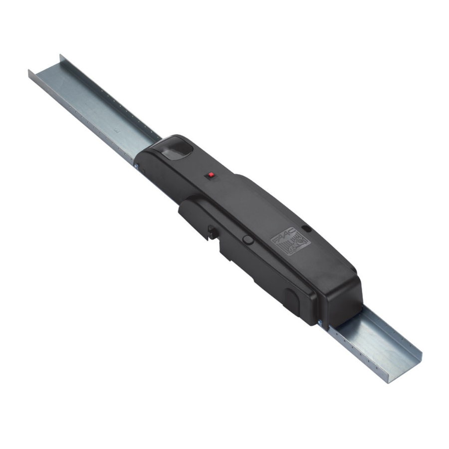
FAAC 550 Manual
Hide thumbs
Also See for 550:
- Manual (47 pages) ,
- Manual for the installer (45 pages) ,
- End user manual (4 pages)
Table of Contents
Advertisement
Quick Links
1. DESCRIPTION AND TECHNICAL SPECIFICATIONS
3. ELECTRICAL INSTALLATION LAYOUT (standard system)
2. DIMENSIONS
4. INSTALLING THE AUTOMATION SYSTEM
4.1. PRELIMINARY CHECKS
4.2. POSITIONING TELESCOPIC ARMS
4.3. POSITIONING OPERATOR/BACK PLATE
4.4. ASSEMBLY SEQUENCE
4.5. ADJUSTING THE COUNTERWEIGHTS
5. MOUNTING GEARED MOTOR UNIT
6. START-UP
6.1. CONNECTING ELECTRONIC CARD
7. TESTING THE AUTOMATION SYSTEM
8. MANUAL OPERATION
9. RETURNING TO NORMAL OPERATION
10. MAINTENANCE
11. REPAIRS
Manufacturer:
FAAC S.p.A.
Address:
Via Benini, 1 - Zola Predosa - Bologna - ITALY
Declares that:
550 - 550 I mod. operator
• is built to be integrated into a machine or to be assembled with other machinery to create a machine under the provisions of
Directive 98/37/CE;
• conforms to the essential safety requirements of the following EEC directives:
73/23 EEC and subsequent amendment 93/68/EEC.
89/336 EEC and subsequent amendment 92/31/EEC and 93/68/EEC
and also declares that the machinery must not be put into service until the machine in which it will be integrated or of which it will
become a component has been identified and declared as conforming to the provisions of Directive 98/37/CE.
Bologna, 01-08-2006
Read this installation manual to the full before you begin installing the product.
The
symbol indicates notes that are important for the safety of persons and for the good condition of the automated system
The
symbol draws your attention to the notes on the characteristics and operation of the product.
CE DECLARATION OF CONFORMITY FOR MACHINES
(DIRECTIVE 98/37/CE)
Notes on reading the instruction
INDEX
The Managing Director
6
A.Bassi
pag.7
pag.7
pag.7
pag.8
pag.8
pag.8
pag.8
pag.8
pag.9
pag.9
pag.9
pag.9
pag.10
pag.10
pag.10
pag.10
pag.10
Advertisement
Table of Contents

Summary of Contents for FAAC 550
- Page 1 Via Benini, 1 - Zola Predosa - Bologna - ITALY Declares that: 550 - 550 I mod. operator • is built to be integrated into a machine or to be assembled with other machinery to create a machine under the provisions of Directive 98/37/CE;...
- Page 2 µ device. ° The 550 automation system allows two operators (550 I + 550) to be installed on the same door. The 550 automation system has been designed and constructed for vehicle access control. Do not use for any other purpose.
- Page 3 • Check that there is an effective earth connection for the geared motor. The 550 automation system is designed to operate various types • double section garage door (fig. 9) of counterbalanced up-and-over garage doors. Fig. 4 shows...
- Page 4 s s i s s i e l i e l i 4.5. ADJUSTING THE COUNTERWEIGHTS 6) Mount the brackets on the transmission shafts and fasten them to the door panel using screws, taking care to maintain On completing mechanical installation, check whether the door perfect alignment.
- Page 5 6.2. CHECKING DIRECTION OF ROTATION - From inside (fig. 17) Insert the hex wrench provided and turn clockwise about half 1) Turn off the power supply to the system. a turn until the stop is reached. 2) Move the door manually to its half open position. Depending on the type of installation, the release device 3) Lock the operator (see section 9) may be on the right (A) or left (B).


Need help?
Do you have a question about the 550 and is the answer not in the manual?
Questions and answers