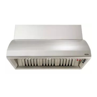
DCS -VH-30HS Use And Installation Manual
The professional vent hoods
Hide thumbs
Also See for DCS-VH-30HS:
- Use and installation manual (18 pages) ,
- Use and installation manual (34 pages)
Table of Contents
Advertisement
Advertisement
Table of Contents

Subscribe to Our Youtube Channel
Related Manuals for DCS DCS-VH-30HS


Summary of Contents for DCS DCS-VH-30HS
- Page 1 _Oynamic _ _yot_, _nc.
- Page 2 Thank you for selecting this DCS ProfessionalVent Hood. Because of its unique features, we have developed this Use and Installation Guide. It contains valuable information on how to properly operate and maintain your new Vent Hood for years of safe and enjoyable cooking.
-
Page 3: Table Of Contents
Before proceeding with installation, please read this installation guide and observe all safety precautions and warnings. NOTE: Installation of this DCS Vent Hood must comply with all local codes. I HPORTANT- Save these instructions for the Local Electrical Inspector's use. -
Page 4: Safety Practices & Precautions
*AII Ventilator Models used Ventilator Use: in DCS Professional Vent TABLE A: Hoods are approved by Vent Hood Model use with Ventilator Model... -
Page 5: Planning The Installation
Vent Hood to avoid personal injury or damage to the Hood. INNER LINER REHOVAL: The DCS Professional Vent Hood has been designed into (2) major assemblies to accommodate easy and safe installation. The following procedure is best done with the Hood on its back on a padded sur- face. - Page 6 Id[_(i][;! DCS Duct Cover (6" or 12" Height) junction box Rough-In Kit Rough-In Kit • junction Through junction box on rough-in kit, connect house wiring to blower motor Model DCS-IB 12 Blower DCS VH 48 Model DCS VH 12 36...
-
Page 7: Vent Hood Installation (With Soffit)
SITE PREPARATION: This DCS Professional Vent Hood has been designed to accommodate installation into a I) soffit structure (ceiling mount), or, for sites without a soffit structure. 2) directly into the wall through holes provided in the rear panel of the vent hood (wall mount). When... -
Page 8: Vent Hood Assembly
INSTALLVENT HOOD INTO SOFFIT: At this point in the installation process, the inner liner should be removed from Hood and set aside (see-Pgs S & 6).With liner set aside, there is clear access to the Soffit mounting holes and wall mounting holes in the rear... -
Page 9: Vent Hood Installation (Without Soffit)
The DCS Duct Cover should be orderedand installed when installing the vent hood in a site without a soffit. DCS offers both a 6"and 12"height Duct Covers. Keep the 6 or 12 inch dimension in mind when allow- ing for clearance between the top of the Vent Hood and the ceiling. (see Fig.4) I. -
Page 10: Finishing The Installation
TO FINISH THE INSTALLATION: I_[_b]! REAR VIEW of VENT HOOD (48" Model Shown) Once the ventilation hood has been mounted in CEILING DRYWALL place it will be necessary to install the electrical service. All electrical work should be done by a qualified electrician and must conform to all local standards. -
Page 11: Duct Information
DCS-VH-48 / DCS-VH 12-36 REQUIREMENTS: DCS recommends the use of 10" round ducting which provides 78.6 sq. In. of surface area. Alternate duct sizes in rectangular style may be used. If a rectangular duct style is used, the duct must equal at least 78.6 sq. In. for best results. (Example- 3-1/4" x 24" duct = 78 sq. In.) Maintain consistent ducting square area as to avoid reduced air flow. - Page 12 3/4" 4-I/2" 23-I12'! 10-114" > " 12-1/4" " -10-174" --... 18-.4"... _o-_14" MODEL DCS IB6 BLOWER ROUGH IN KIT MODEL DCS IBI2 BLOWER ROUGH IN KIT MODEL DCS 186 BLOWER VOLTS HZ AMPS DUCT 7" ROUND MODEL DCS IBI2 BLOWER 1200 10"...
-
Page 13: Howto Obtain Service
I) Is the circuit breaker tripped or the fuse blown? 2) Is there a power outage in the area? For warranty service, contact your local DCS authorized service agency. Provide him with the Model Number, Serial Number, and date of installation, and a brief description of the problem. -
Page 14: Warranty
DCS to be defective. Replacement will be EO.B. DCS, and DCS will not be liable for any transportation costs, labor costs, or export duties. This warranty... - Page 15 48" VENT HOOD WIRING DIAGRAM 1200 CFM MOTOR JUNCTION BOX /L,> /HI BL/_ROUND>I iWHT I GRH I MOTOR BLOWER PLUG MOTOR CONNECTORS: WriT I1:234s61 FEMALE :2 3 6 I MALE ..............................................................• USED ON I HS MODELS LEFT HEAT USED ON RIGHT HEAT i ONLY...
- Page 16 JUNCTION 36" / 30" VENT HOOD WIRING DIAGRAM (LI) 600 CFM MOTOR BLOWER MOTOR CONNECTORS: FEMALE MALE USED ON HEAT I HS MODELS LIGHT i ONLY LEFT LIGHT RIGHT LIGHT HEAT LIGHT SWITCH WN-2 WN-I...
- Page 18 As product improvement is an ongoing process at DCS, we reserve the right to change specifications or design without notice, Part No. 10607r5 Litho in USA 06/2001...
Need help?
Do you have a question about the DCS-VH-30HS and is the answer not in the manual?
Questions and answers